IPC-TM-650 EN 2022 试验方法--.pdf - 第63页
FED-STD-191 The Institute for Int erconnecting and Packaging E lectronic Circuits 2215 S anders Road • Northbrook, IL 60062-6135 Material in this T est M ethods Manual was vol untaril y establis hed by T echni cal Commit…
The Institute for Interconnecting and Packaging Electronic Circuits
2215 Sanders Road • Northbrook, IL 60062-6135
Material in this Test Methods Manual was voluntarily established by Technical Committees of the IPC. This material is advisory only
and its use or adaptation is entirely voluntary. IPC disclaims all liability of any kind as to the use, application, or adaptation of this
material. Users are also wholly responsible for protecting themselves against all claims or liabilities for patent infringement.
Equipment referenced is for the convenience of the user and does not imply endorsement by the IPC.
Page 1 of 1
IPC-TM-650
TEST
METHODS
MANUAL
1
.0
Scope
This
test
method
identifies
the
major
areas
of
concern
during
a
visual
examination
and
describes
the
recom¬
mended
procedures.
2
.0
Application
Documents
None.
3
.0
Test
Specimen
Any
representative
clad
or
unclad
sample
of
printed
wiring
material.
4
.0
Equipment/Apparatus
Magnifier
or
microscope
capable
of
up
to
30X
magnification,
having
a
reticle
capable
of
measuring
to
the
nearest
0.001
in.
5
.0
Procedures
5.1
Pinholes
Pinholes
are
predetermined
by
visual
exami¬
nation
using
not
less
than
10X
magnification
on
the
specimen.
Copper
surfaces
should
be
prepared
by
cleaning
or
light
etch¬
ing.
5.2
Pits
and
Dents
The
maximum
total
point
count
for
pits
and
dents,
per
square
foot
of
panel
inspected
is
determined
as
follows:
Longest
Dimension
(inch)
Point
Value
0.000
to
0.010
inclusive
1
0.
01
1
to
0.020
inclusive
2
0.021
to
0.030
inclusive
4
0.031
to
0.040
inclusive
7
over
0.040
30
Number
2.1.5
Subject
Surface
Examination,
Unclad
and
Metal-Clad
Material
Date
12/82
Revision
A
Originating
Task
Group
N/A
5.3
Scratches
Scratches
can
be
measured
with
the
use
of
a
microscope
(30X
maximum).
5.4
Wrinkles
Wrinkles
should
be
viewed
by
normal
or
cor¬
rected
20/20
vision.
5.5
Inclusions
Inclusions
should
be
measured
using
18X
to
30X
magnification.
6
.0
Notes
For
additional
reference
see:
IPC-CF-150:
Copper
Foil
IPC-A-600:
Acceptability
of
Printed
Boards
MIL-P-1
3949:
Laminate
Materials
Pits
and
dents
should
be
determined
visually
using
not
less
than
10X
magnification
on
the
specimen.
FED-STD-191
The Institute for Interconnecting and Packaging Electronic Circuits
2215 Sanders Road • Northbrook, IL 60062-6135
Material in this Test Methods Manual was voluntarily established by Technical Committees of the IPC. This material is advisory only
and its use or adaptation is entirely voluntary. IPC disclaims all liability of any kind as to the use, application, or adaptation of this
material. Users are also wholly responsible for protecting themselves against all claims or liabilities for patent infringement.
Equipment referenced is for the convenience of the user and does not imply endorsement by the IPC.
Page 1 of 1
IPC-TM-650
TEST
METHODS
MANUAL
1
.0
Scope
This
method
is
designed
to
determine
the
thick¬
ness
of
woven
glass
fabric,
such
as
E-glass,
S-glass,
and
quartz,
used
as
reinforcement
in
prepreg
(resin-impregnated
glass
fabric,
or
B-stage).
It
is
applicable
for
glass
fabric
inspection
before
and
after
impregnation.
2
.0
Applicable
Documents
3
.0
Test
Specimens
3.1
Size
Specimen
size
of
101
.6
x
1
01
.6
mm
[4.0
x
4.0
in]
is
recommended;
specimens
used
for
determination
of
resin
content
by
Burn
Off
Method
may
be
used.
Specimens
shall
be
of
sufficient
size
to
insure
that
all
points
of
the
pressure
foot
of
the
thickness
gauge
shall
be
at
least
6.4
mm
[0.25
in]
from
the
edge
of
the
specimen.
3.2
Quantity
and
Sampling
Unless
otherwise
specified,
three
pieces
of
material
shall
be
cut
one
each
from
three
sample
sheets.
Specimens
shall
be
cut
with
the
edges
on
a
bias
to
the
orientation
of
the
fabric.
Specimens
shall
be
free
of
folds,
creases,
knots
or
other
distortions
which
are
not
repre¬
sentative
of
the
material
surface.
4
.0
Apparatus
or
Material
4.1
Muffle
furnace
Muffle
furnace
that
is
capable
of
main¬
taining
550
+/-50℃
[1022
±90°F]-
4.2
Thickness
Gage
(Dead
weight
type)
A
dead
weight
type
thickness
gage
equipped
with
a
dial
graduated
to
read
with
a
precision
of
0.0025
mm
[0.0001
in]
shall
be
used.
The
pressure
foot
shall
be
circular
with
a
diameter
of
6.35
±0.025
mm
[0.25
±0.001
in],
and
with
the
moving
parts
weighted
to
apply
a
total
load
of
173
±14
kPa
(25
±2
psi)
to
the
specimen.
The
anvil
shall
be
not
less
than
6.35
mm
[0.250
in]
in
diameter.
The
micrometer
shall
be
capable
of
repeating
its
readings
to
0.0013
mm
[0.00005
in]
at
zero
setting
or
on
a
steel
gage
block.
Number
2.1.6
Subject
Thickness
of
Glass
Fabric
Date
Revision
12/94
B
Originating
Task
Group
MIL-P-13949
Test
Methods
Task
Group
(7-1
1b)
5.0
Procedure
5.1
Preparation
of
Prepreg
Specimens
Place
specimens
in
a
muffle
furnace
at
550±50℃
[1022
±90°
F],
for
a
period
of
time
necessary
to
assure
complete
removal
of
the
organics
(resin).
After
removal
from
the
muffle
furnace,
the
specimens
shall
be
cooled
to
room
temperature.
5.2
Thickness
Determination
The
specimen
shall
be
placed
on
the
thickness
gauge
anvil,
and
the
pressure
foot
shall
be
closed
onto
the
specimen
at
a
location
outside
the
area
to
be
measured.
The
pressure
foot
shall
be
backed
off
to
a
distance
of
0.008
to
0.01
mm
[0.0003
to
0.0004
in],
the
specimen
moved
to
the
measurement
position,
and
the
pres¬
sure
foot
then
released
onto
the
specimen.
The
pressure
foot
shall
be
allowed
to
rest
there
for
a
minimum
of
5
seconds.
The
dial
reading
shall
then
be
taken
to
the
nearest
0.0025
mm
[0.0001
in].
5.3
Evaluation
Record
each
reading
and
report
the
average
of
three
measurements
to
the
nearest
0.025
mm
[0.001
in].
6.0
Notes
See
Federal
Test
Method
Standard
No.
191,
Method
No.
5050
for
additional
information
and
background
on
this
procedure.
The Institute for Interconnecting and Packaging Electronic Circuits
2215 Sanders Road • Northbrook, IL 60062-6135
Material in this Test Methods Manual was voluntarily established by Technical Committees of the IPC. This material is advisory only
and its use or adaptation is entirely voluntary. IPC disclaims all liability of any kind as to the use, application, or adaptation of this
material. Users are also wholly responsible for protecting themselves against all claims or liabilities for patent infringement.
Equipment referenced is for the convenience of the user and does not imply endorsement by the IPC.
Page 1 of 1
IPC-TM-650
TEST
METHODS
MANUAL
1
.0
Scope
This
method
is
designed
to
determine
the
weight
of
a
fabric
by
use
of
a
small
specimen.
It
is
appropriate
for
woven
or
non
woven
fabrics
made
with
glass
or
other
inor¬
ganic
yarns,
or
made
with
organic
fibers
or
yarns.
2
.0
Applicable
Documents
None
3
.0
Test
Specimens
3.1
Test
Specimen
Configuration
Unless
otherwise
specified,
the
specimen
shall
consist
of
at
least
2
pieces
of
fabric
with
a
maximum
size
of
1
27
x
1
78
mm
[5.0
x
7.0
in]
and
a
minimum
of
98
x
98
mm
[3.88
x
3.88
in].
The
total
area
shall
be
greater
than
29,000
sq
mm
[45
sq.
in].
For
example,
three
pcs.
of
1
02
x
1
02
mm
[4x4
in]
with
a
total
area
of
30,968
sq
mm
[48
sq.
in].
3.2
Quantity
and
Sampling
Specimens
shall
be
taken
from
the
fabric
roll
(as
supplied
by
the
manufacturer)
no
closer
to
the
selvage
(or
cut
edge)
than
a
distance
equal
to
one-tenth
of
the
width
of
the
roll.
Unless
otherwise
specified,
three
specimens
shall
be
taken
from
the
roll
at
randomly
selected
locations.
4
.0
Apparatus
or
Material
4.1
An
analytical
balance
capable
of
weighing
to
0.001
gm.
4.2
Cutting
Equipment
A
punch
die
or
steel
rule
die
capable
of
cutting
the
specimens
to
a
size
per
3.1
and
to
within
0.38
mm
[0.015
in].
Alternately
a
razor
blade
knife,
or
equivalent,
plus
a
caliper,
or
equivalent
measuring
device,
may
be
used
provided
the
precision
requirement
is
met
and
the
fabric
edges
are
cleanly
cut.
Number
2.1.6.1
(renumbered
from
2.3.12)
Subject
Weight
of
Fabric
Reinforcements
Date
Revision
12/94
Originating
Task
Group
MIL-P-13949
Test
Methods
Task
Group
(7-1
1b)
5.0
Procedure
5.1
Prepare
a
specimen
by
cutting
the
specified
pieces
in
accordance
with
3.0.
Carefully
handle
the
pieces
to
prevent
loss
of
yarns
or
fibers
from
the
cut
edges.
When
applicable,
the
edges
shall
be
cut
on
a
bias
to
the
orientation
of
the
fab¬
ric.
If
not
using
a
die,
measure
the
specimen
dimensions
to
the
nearest
0.38
mm
[0.01
5
in].
5.2
Determine
the
weight
of
the
specimen
to
within
0.1%
on
the
balance.
(Note:
care
must
be
taken
so
that
any
loose
yarns
unraveling
from
the
cut
are
also
weighed
with
the
speci¬
men.)
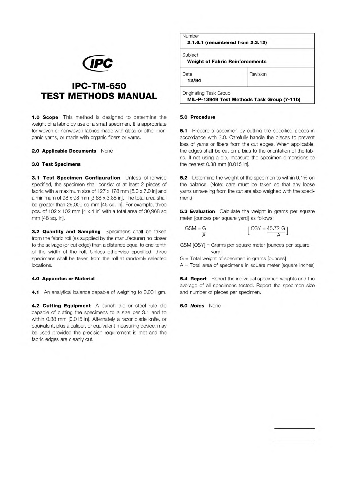
5.3
Evaluation
Calculate
the
weight
in
grams
per
square
meter
[ounces
per
square
yard]
as
follows:
GSM
=
G
r
OSY
=
45.72
G
1
a
L
—
GSM
[OSY]
二
Grams
per square
meter
[ounces
per
square
yard]
G
=
Total
weight
of
specimen
in
grams
[ounces]
A
二
Total
area
of
specimens
in
square
meter
[square
inches]
5.4
Report
Report
the
individual
specimen
weights
and
the
average
of
all
specimens
tested.
Report
the
specimen
size
and
number
of
pieces
per
specimen.
6.0
Notes
None