IPC-TM-650 EN 2022 试验方法--.pdf - 第457页
Figure 17 T est Fixture Construction, Older Design (Continued) IPC-TM-650 Page 25 o f 25 ASSEMBLY 51 DETAIL C countersink 51 dio. steel ball Clamping force DETAIL A #4一40 X 6.35 mm s 4 places IPC-2555-17 • • ' CLAMP…
4 Measurement Apparatus
4.1 Split-Cylinder Resonator
The method employs a
split-cylinder resonator, which is a cylindrical cavity separated
into two halves of equal length, with a dielectric substrate
placed in the gap between the two cavity sections. The split-
cylinder resonator must be constructed to allow an adjustable,
variable gap between the two cavity sections for introduction
of the dielectric substrate. Additional details about the con-
struction of a split-post resonator are given in the references
described in 6.2. Over the years there have been commercial
manufacturers of this fixture.
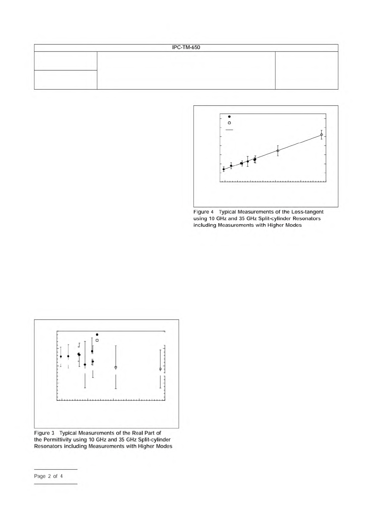
In order to excite and detect the desired fundamental TE
011
resonant mode in the split-cylinder resonator, a coupling loop
is introduced, through a small hole in the cavity wall, in each
of the two cavity regions. The plane of the coupling loop
should be parallel to the plane of the sample, in order to allow
maximum interaction with the vertical component of the mag-
netic field. Each of the coupling loops is connected to a
coaxial transmission line that is connected to the input port of
a network analyzer. To minimize the effect of coupling losses,
the distance to which the loops extend radially into each of the
cavity sections must also be adjustable. In addition to the fun-
damental TE
011
mode, higher modes can be used to extend
the measurement frequency. Typical measurements on fused
silica with higher mode measurements are shown in Figures 3
and 4.
4.2 Network Analyzer
A scalar or vector network analyzer
is necessary to perform the measurement with the split-
cylinder resonator. Commercially available network analyzers
operate over various frequency ranges, so care is needed to
ensure that the network analyzer covers the necessary fre-
quency range for the particular split-cylinder resonator used.
4.3 Digital Micrometer
The dielectric substrate thickness
can be measured with a digital micrometer with a minimal
resolution of 0.001 mm [0.000039 in].
5 Procedure
5.1
Turn on the network analyzer and allow the unit to
warm-up and stabilize according to the manufacturer’s
instructions.
5.2
Connect the network analyzer’s two input ports to the
split-cylinder resonator’s coupling loops using coaxial trans-
mission lines.
5.3
Measure the thickness of the substrate over several
locations using a digital micrometer, and compute the mean
substrate thickness.
5.4
Determine split-cylinder resonator properties. The
length, radius and conductivity of the split-cylinder resonator
must be known before the substrate relative permittivity and
loss tangent can be calculated. If these variables have not
been already determined, the following procedure can be
used:
IPC-25513-3
3.90
10 20
Frequency (GHz)
30 40 50
3.85
3.80
3.75
3.70
Relative Permittivity
10 GHz Split-Cylinder Resonator
35 GHz Split-Cylinder Resonator
TE
011
TE
013
TE
021
TE
023
TE
017
TE
025
TE
011
TE
013
TE
015
IPC-25513-4
7x10
-4
6
5
4
3
2
1
0
10 20
Frequency (GHz)
30 40 50
Loss Tangent
35 GHz Split-Cylinder Resonator
Linear Least Squares Fit
10 GHz Split-Cylinder Resonator
TE
011
TE
013
TE
021
TE
023
TE
017
TE
025
TE
011
TE
013
TE
015
Number
2.5.5.13
Subject
Relative Permittivity and Loss Tangent Using a Split-Cylinder
Resonator
Date
01/07
Revision
IPC-TM-650
Figure
4
Typical
Measurements
of
the
Loss-tangent
using
10
GHz
and
35
GHz
Split-cylinder
Resonators
including
Measurements
with
Higher
Modes
Figure
3
Typical
Measurements
of
the
Real
Part
of
the
Permittivity
using
10
GHz
and
35
GHz
Split-cylinder
Resonators
including
Measurements
with
Higher
Modes
Page
2
of
4
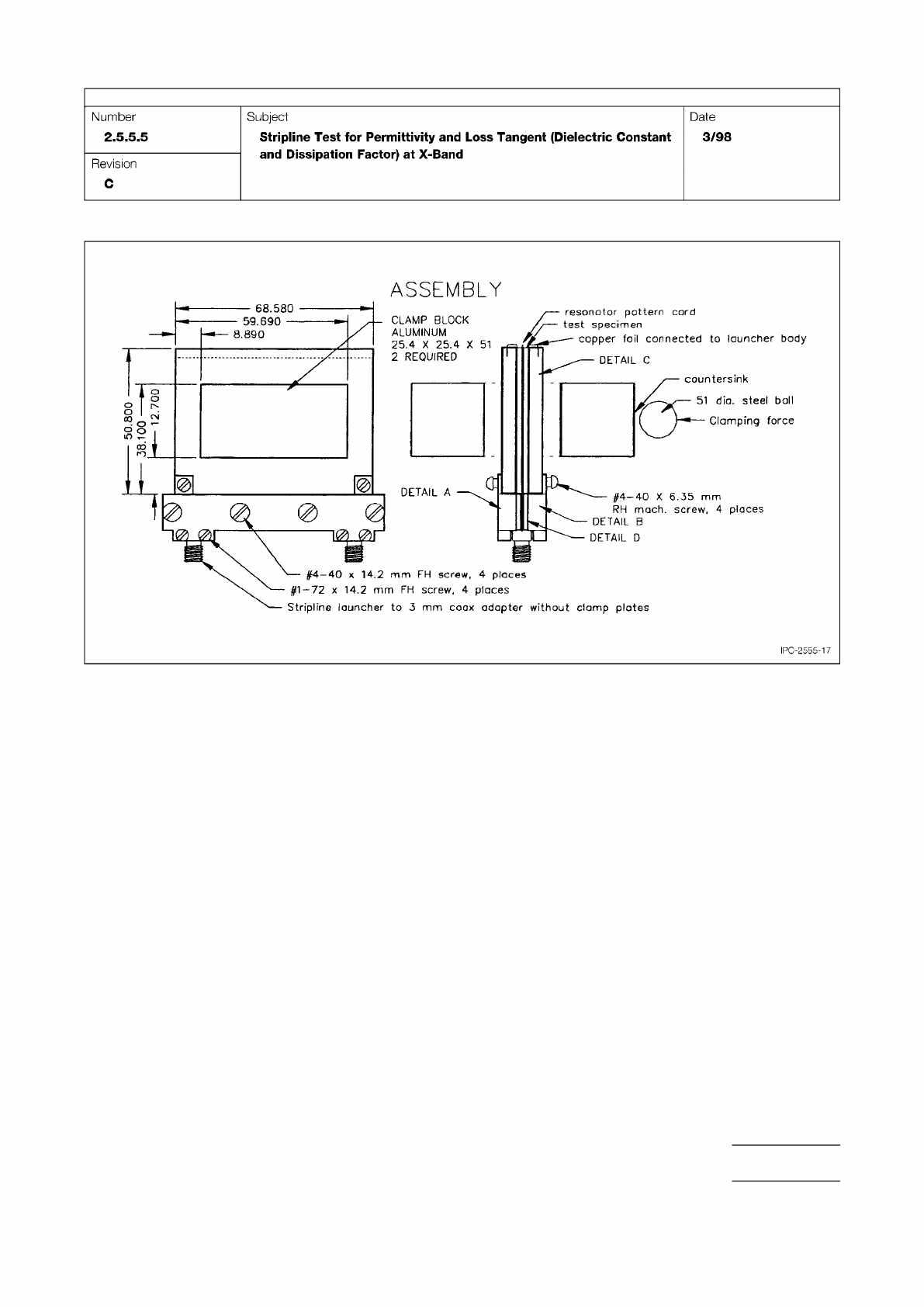
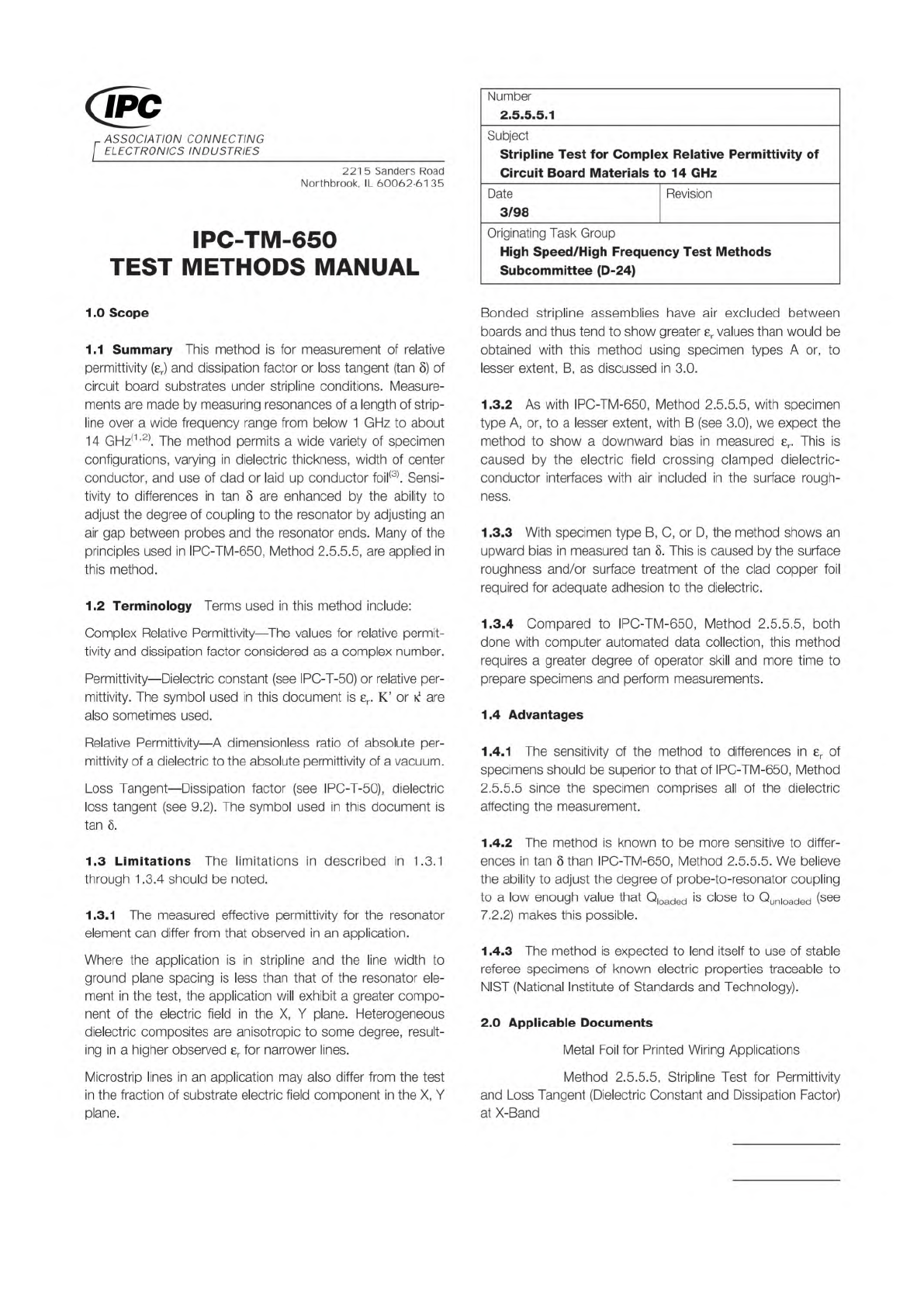
Figure 17 Test Fixture Construction, Older Design (Continued)
IPC-TM-650
Page 25 of 25
ASSEMBLY
51
DETAIL
C
countersink
51
dio.
steel
ball
Clamping
force
DETAIL
A
#4一40
X
6.35
mm
s
4
places
IPC-2555-17
•
•
'
CLAMP
BLOCK
ALUMINUM
25.4
X
25.4
X
2
REQUIRED
—
68.580
-
59.690
-
8.890
RH
mach.
screw,
4
places
DETAIL
B
DETAIL
D
resonator
pattern
cord
test
specimen
copper
foil
connected
to
launcher
body
#1-72
x
14.2
mm
FH
screw,
4
places
Stripline
launcher
to
3
mm
coax
adapter
without
clamp
plotes
#4—40
x
14,2
mm
FH
screw.
Number
2.5.5.5
Subject
Stripline
Test
for
Permittivity
and
Loss
Tangent
(Dielectric
Constant
and
Dissipation
Factor)
at
X-Band
Date
3/98
Revision
C
oo
-
o
1n
IPC-MF-150
IPC-TM-650
Material in this Test Methods Manual was voluntarily established by Technical Committees of the IPC. This material is advisory only
and its use or adaptation is entirely voluntary. IPC disclaims all liability of any kind as to the use, application, or adaptation of this
material. Users are also wholly responsible for protecting themselves against all claims or liabilities for patent infringement.
Equipment referenced is for the convenience of the user and does not imply endorsement by the IPC.
Page 1 of 11
Number
r
ASSOCIATION
CONNECTING
/
ELECTRONICS
INDUSTRIES
221
5
Sanders
Road
Northbrook,
IL
60062-6135
IPC-TM-650
TEST
METHODS
MANUAL
1
.0
Scope
1.1
Summary
This
method
is
for
measurement
of
relative
permittivity
(er)
and
dissipation
factor
or
loss
tangent
(tan
S)
of
circuit
board
substrates
under
stripline
conditions.
Measure¬
ments
are
made
by
measuring
resonances
of
a
length
of
strip¬
line
over
a
wide
frequency
range
from
below
1
GHz
to
about
14
GHz(1,2).
The
method
permits
a
wide
variety
of
specimen
configurations,
varying
in
dielectric
thickness,
width
of
center
conductor,
and
use
of
clad
or
laid
up
conductor
foil(3).
Sensi¬
tivity
to
differences
in
tan
8
are
enhanced
by
the
ability
to
adjust
the
degree
of
coupling
to
the
resonator
by
adjusting
an
air
gap
between
probes
and
the
resonator
ends.
Many
of
the
principles
used
in
IPC-TM-650,
Method
255.5,
are
applied
in
this
method.
1.2
Terminology
Terms
used
in
this
method
include:
Complex
Relative
Permittivity
―
The
values
for
relative
permit¬
tivity
and
dissipation
factor
considered
as
a
complex
number.
Permittivity
—
Dielectric
constant
(see
IPC-T-50)
or
relative
per¬
mittivity.
The
symbol
used
in
this
document
is
er.
K'
or
k
are
also
sometimes
used.
Relative
Permittivity
—
A
dimensionless
ratio
of
absolute
per¬
mittivity
of
a
dielectric
to
the
absolute
permittivity
of
a
vacuum.
Loss
Tangent
—
Dissipation
factor
(see
IPC-T-50),
dielectric
loss
tangent
(see
9.2).
The
symbol
used
in
this
document
is
tan
8.
1.3
Limitations
The
limitations
in
described
in
1
.3.1
through
1.3.4
should
be
noted.
1.3.1
The
measured
effective
permittivity
for
the
resonator
element
can
differ
from
that
observed
in
an
application.
Where
the
application
is
in
stripline
and
the
line
width
to
ground
plane
spacing
is
less
than
that
of
the
resonator
ele¬
ment
in
the
test,
the
application
will
exhibit
a
greater
compo¬
nent
of
the
electric
field
in
the
X,
Y
plane.
Heterogeneous
dielectric
composites
are
anisotropic
to
some
degree,
result¬
ing
in
a
higher
observed
er
for
narrower
lines.
Microstrip
lines
in
an
application
may
also
differ
from
the
test
in
the
fraction
of
substrate
electric
field
component
in
the
X,
Y
plane.
2.5.5.5.1
Subject
Stripline
Test
for
Complex
Relative
Permittivity
of
Circuit
Board
Materials
to
14
GHz
Date
Revision
3/98
Originating
Task
Group
High
Speed/High
Frequency
Test
Methods
Subcommittee
(D-24)
Bonded
stripline
assemblies
have
air
excluded
between
boards
and
thus
tend
to
show
greater
8r
values
than
would
be
obtained
with
this
method
using
specimen
types
A
or,
to
lesser
extent,
B,
as
discussed
in
3.0.
1.3.2
As
with
IPC-TM-650,
Method
2.
5.
5.5,
with
specimen
type
A,
or,
to
a
lesser
extent,
with
B
(see
3.0),
we
expect
the
method
to
show
a
downward
bias
in
measured
er.
This
is
caused
by
the
electric
field
crossing
clamped
dielectric¬
conductor
interfaces
with
air
included
in
the
surface
rough¬
ness.
1.3.3
With
specimen
type
B,
C,
or
D,
the
method
shows
an
upward
bias
in
measured
tan
5.
This
is
caused
by
the
surface
roughness
and/or
surface
treatment
of
the
clad
copper
foil
required
for
adequate
adhesion
to
the
dielectric.
1.3.4
Compared
to
IPC-TM-650,
Method
2.
5.5.
5,
both
done
with
computer
automated
data
collection,
this
method
requires
a
greater
degree
of
operator
skill
and
more
time
to
prepare
specimens
and
perform
measurements.
1.4
Advantages
1.4.1
The
sensitivity
of
the
method
to
differences
in
er
of
specimens
should
be
superior
to
that
of
IPC-TM-650,
Method
255.5
since
the
specimen
comprises
all
of
the
dielectric
affecting
the
measurement.
1
.4.2
The
method
is
known
to
be
more
sensitive
to
differ¬
ences
in
tan
8
than
IPC-TM-650,
Method
2.5.55
We
believe
the
ability
to
adjust
the
degree
of
probe-to-resonator
coupling
to
a
low
enough
value
that
Q,oaded
is
close
to
Qun|Oaded
(see
7.2.2)
makes
this
possible.
1
.4.3
The
method
is
expected
to
lend
itself
to
use
of
stable
referee
specimens
of
known
electric
properties
traceable
to
NIST
(National
Institute
of
Standards
and
Technology).
2
.0
Applicable
Documents
Metal
Foil
for
Printed
Wiring
Applications
Method
2.
5.5.
5,
Stripline
Test
for
Permittivity
and
Loss
Tangent
(Dielectric
Constant
and
Dissipation
Factor)
at
X-Band