IPC-TM-650 EN 2022 试验方法--.pdf - 第515页
5.2.1.2 Verif ication Fi eld C heck The method inclu de s a verification procedure to test the success of the measurement set-up in determining propagation delay. The ve rification pro- cedure f ollows t he same steps us…
5.2.1.1 Establishing the Electrical Length of the Mea-
surement System
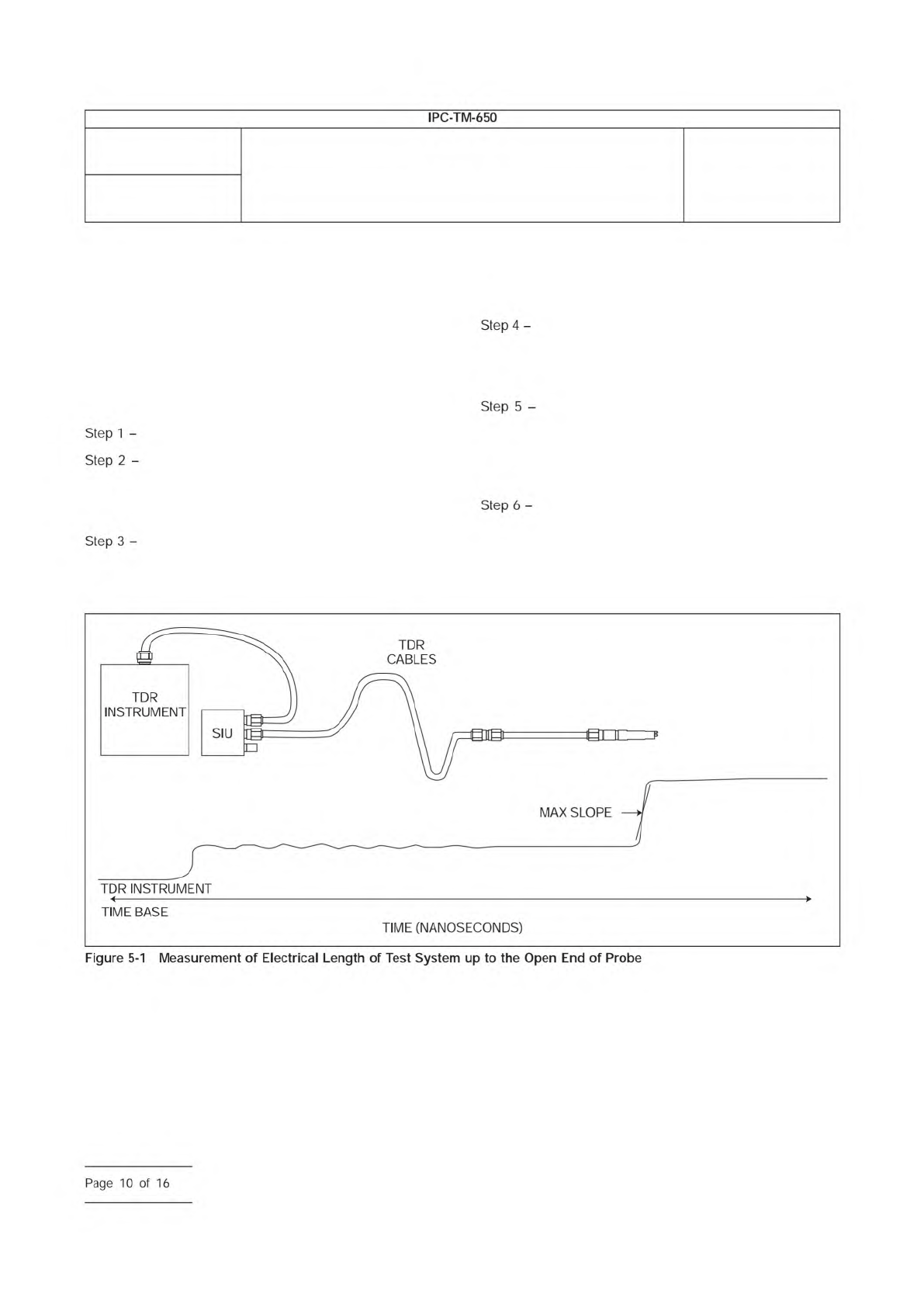
To assist in tracking the repeatability and
suitability of the measurement system, the method includes
the following procedure to determine the electrical length of
the TDR measurement system from the TDR sampler to the
end of the probe tip. The user may record this time value for
a given set-up over subsequent measurement sessions in
order to verify consistency in system performance over long
time periods.
Turn on the TDR source and enable triggering.
Hold the probe in the air away from other objects
and surfaces and set the waveform epoch to include both the
incident signal from the TDR source and the superimposed
reflection signal from the probe tip (see Figure 5-1).
For this epoch, adjust the number of sample points
to achieve a sample density of no less than 2 S/ps. For
example, this is achieved with a time record of 4,000 sample
points and a waveform epoch that is 2,000 ps long (10 divi-
sion x 200 ps/div).
Identify the arrival time t
inc
of the incident pulse edge
as 50% of the incident amplitude. For step signals, use the
difference of average pre- and post-step voltage levels to
establish the incident amplitude.
Identify the arrival time t
refl
of the reflection pulse
edge as 50% of the reflection amplitude. For step signals, use
the difference of average pre- and post-step voltage levels to
establish the reflection amplitude (this is often near the region
of maximum dV/dt.)
Record the system’s electrical length as one half of
the round-trip time: t
syslen
= (t
ref
- t
inc
)/2.
IPC-25511-5-1
(Note: The optional static isolation unit (SIU) is a protection device designed to eliminate static discharge damage to the TDR sampling
head.)
Number
2.5.5.11
Subject
Propagation Delay of Lines on Printed Boards by TDR
Date
04/2009
Revision
IPC-TM-650
Step
1
-
Step
2
-
Step
3
-
Step
4
-
Step
5
-
Step
6
-
Page
10
of
16
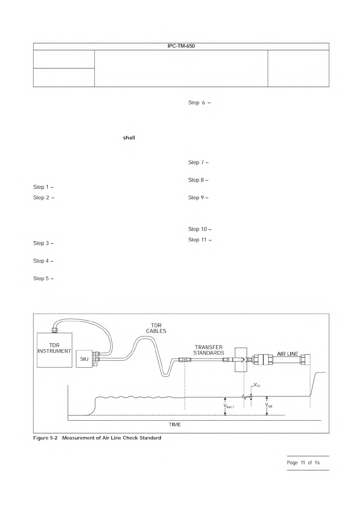
5.2.1.2 Verification Field Check
The method includes a
verification procedure to test the success of the measurement
set-up in determining propagation delay. The verification pro-
cedure follows the same steps used when characterizing test
specimens, but uses known and precise delay verification ele-
ments (as described in 4.3.7.) The user
perform this field
check prior to reporting delay results from the test specimens.
The user must fabricate their own transition cards that allow
electrical connection to the end of the coaxial air lines using
the probes of the measurement set-up. Figure 5-2 shows the
probe contacting a transition to coaxial adapter.
Turn on the TDR source and enable triggering.
Connect the probe-to-coax adapter to one end of
the longer air line check standard, leaving the opposite end
open circuit. For beadless air lines, this requires the addition
of an open circuit coax adapter at the far end in order to hold
the center conductor in place. As with all coax connections,
use the appropriate connection torque (see 4.3.1).
Connect the probe to the contact pads of the tran-
sition adapter.
Adjust the waveform epoch to capture the reflection
signal from the far end of the longer open circuit air line.
Measure the arrival time of the reflection signal from
the open circuit by testing when the reflection signal crosses
V
REF
as defined above for the user-selected value of x. Record
the arrival time value as t
T1
.
Connect the same probe-to-coax adapter used
above in Step 2 to one end of the shorter air line check stan-
dard, leaving the opposite end open circuit. For beadless air
lines, this requires the addition of an open circuit coax adapter
at the far end in order to hold the center conductor in place.
Use the same open circuit coax adapter used in Step 2. As
with all coax connections, use the appropriate connection
torque (see 4.3.1).
Connect the probe to the contact pads of the tran-
sition adapter.
Adjust the waveform epoch to capture the reflection
signal from the far end of the shorter open circuit air line.
Measure the arrival time of the reflection signal from
the open circuit by testing when the reflection signal crosses
V
REF
as defined above for the user-selected value of x. Record
the arrival time value as t
T2
.
Calculate the propagation time t
p
= t
T1
- t
T2
.
Compare t
p
to the difference in delay values pro-
vided by the air line manufacturer or calibration lab, and test
whether or not the measurement system t
p
agrees with the
standards to within the uncertainty target of the measurement
system or desired uncertainty required by the test specimens.
The propagation time will not be known to contain a better
resolution than that established in 4.1.2.
IPC-25511-5-2
Number
2.5.5.11
Subject
Propagation Delay of Lines on Printed Boards by TDR
Date
04/2009
Revision
SIU
TIME
TDR
INSTRUMENT
Step
1
-
Step
2
-
Step
3
-
Step
4
-
Step
5
-
Step
6
-
Step
7
-
Step
8
-
Step
9
-
Step
10
-
Step
11
-
Figure
5-2
Measurement
of
Air
Line
Check
Standard
IPC-TM-650
—
Page
11
of
16
ASTM-D-257
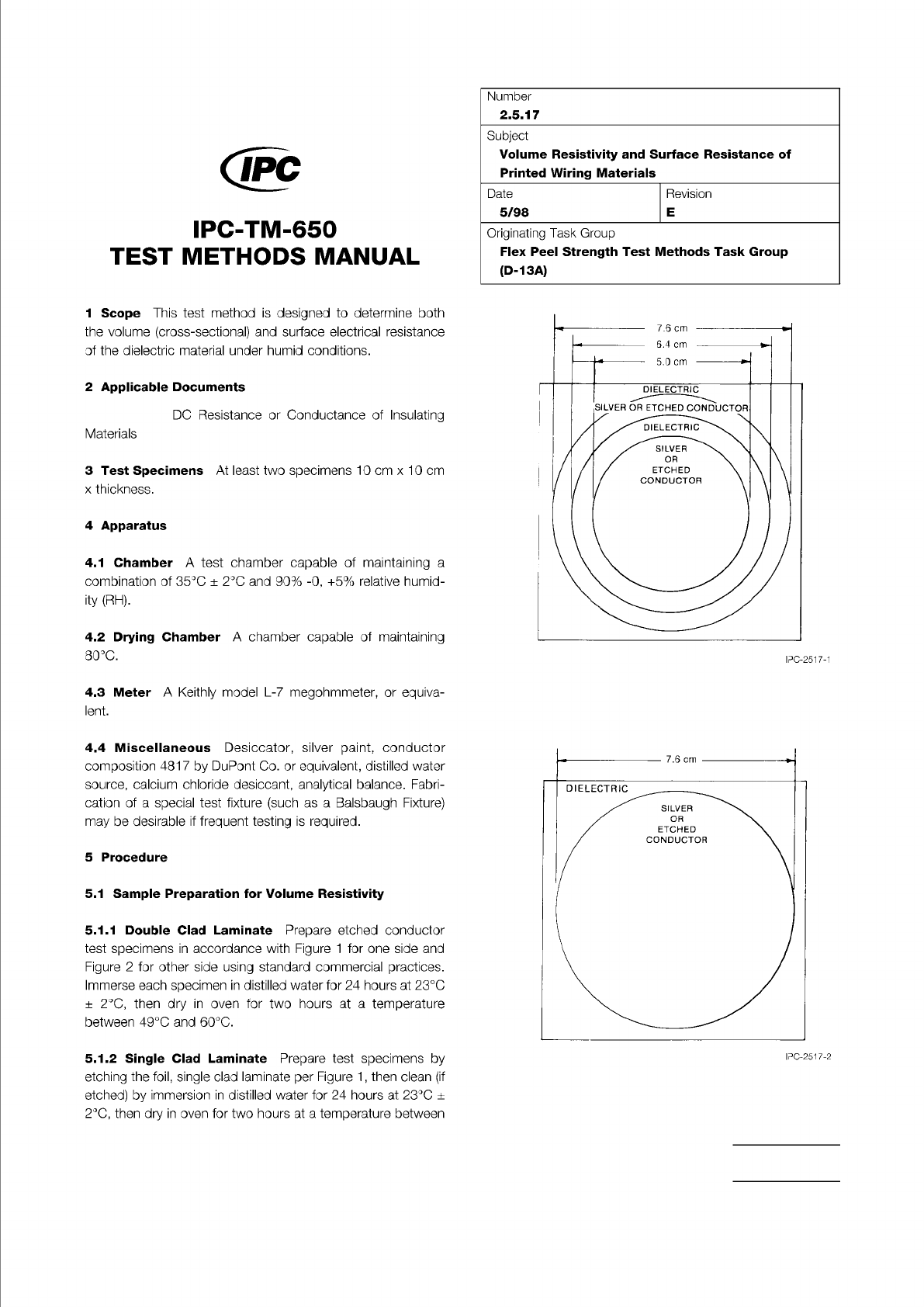
Figure 1 Volume and Surface Resistivity Test Pattern.
(Side 1)
Figure 2 Volume and Surface Resistivity Test Pattern.
(Side 2)
The Institute for Interconnecting and Packaging Electronic Circuits
2215 Sanders Road • Northbrook, IL 60062
Material in this Test Methods Manual was voluntarily established by Technical Committees of the IPC. This material is advisory only
and its use or adaptation is entirely voluntary. IPC disclaims all liability of any kind as to the use, application, or adaptation of this
material. Users are also wholly responsible for protecting themselves against all claims or liabilities for patent infringement.
Equipment referenced is for the convenience of the user and does not imply endorsement by the IPC.
Page 1 of 2
IPC-TM-650
TEST
METHODS
MANUAL
1
Scope
This
test
method
is
designed
to
determine
both
the
volume
(cross-sectional)
and
surface
electrical
resistance
of
the
dielectric
material
under
humid
conditions.
2
Applicable
Documents
DC
Resistance
or
Conductance
of
Insulating
Materials
3
Test
Specimens
At
least
two
specimens
10
cm
x
10
cm
x
thickness.
4
Apparatus
4.1
Chamber
A
test
chamber
capable
of
maintaining
a
combination
of
35℃
±
2
℃
and
90%
-0,
+5%
relative
humid¬
ity
(RH).
4.2
Drying
Chamber
A
chamber
capable
of
maintaining
80℃.
4.3
Meter
A
Keithly
model
L-7
megohmmeter,
or
equiva¬
lent.
4.4
Miscellaneous
Desiccator,
silver
paint,
conductor
composition
4817
by
DuPont
Co.
or
equivalent,
distilled
water
source,
calcium
chloride
desiccant,
analytical
balance.
Fabri¬
cation
of
a
special
test
fixture
(such
as
a
Balsbaugh
Fixture)
may
be
desirable
if
frequent
testing
is
required.
5
Procedure
5.1
Sample
Preparation
for
Volume
Resistivity
5.1.1
Double
Clad
Laminate
Prepare
etched
conductor
test
specimens
in
accordance
with
Figure
1
for
one
side
and
Figure
2
for
other
side
using
standard
commercial
practices.
Immerse
each
specimen
in
distilled
water
for
24
hours
at
23℃
±
2
℃,
then
dry
in
oven
for
two
hours
at
a
temperature
between
49℃
and
60℃.
5.1.2
Single
Clad
Laminate
Prepare
test
specimens
by
etching
the
foil,
single
clad
laminate
per
Figure
1
,
then
clean
(if
etched)
by
immersion
in
distilled
water
for
24
hours
at
23℃
±
2
℃,
then
dry
in
oven
for
two
hours
at
a
temperature
between
Number
2.5.17
Subject
Volume
Resistivity
and
Surface
Resistance
of
Printed
Wiring
Materials
Date
Revision
5/98
E
Originating
Task
Group
Flex
Peel
Strength
Test
Methods
Task
Group
(D-13A)