IPC-TM-650 EN 2022 试验方法--.pdf - 第640页
Figure 2 AC P ower Entry Mounting Suggestion Junction Box Duplex Receptacle Ground Fastener Enclosure Wa ll Metal Cover Line Filter AC Line Cord Inside Outside IPC-TM-650 Number Subject Date Revision Page 2 of 3 2.5.33.4…
ANSI/J-STD-001
Figure 1 Enclosure Construction Suggestion
51 cm
81 cm
43 cm
LID
WOOD
SHEET METAL
OR WIRE MESH
The Institute for Interconnecting and Packaging Electronic Circuits
2215 Sanders Road • Northbrook, IL 60062
Material in this Test Methods Manual was voluntarily established by Technical Committees of the IPC. This material is advisory only
and its use or adaptation is entirely voluntary. IPC disclaims all liability of any kind as to the use, application, or adaptation of this
material. Users are also wholly responsible for protecting themselves against all claims or liabilities for patent infringement.
Equipment referenced is for the convenience of the user and does not imply endorsement by the IPC.
Page 1 of 3
Number
IPC-TM-650
TEST
METHODS
MANUAL
1
Scope
The
following
information
is
a
supporting
docu¬
ment
in
support
of
Method
2.5.33.
The
test
methods
within
this
group
of
procedures
can
be
falsely
influenced
by
radio
frequency
interference
and
electromagnetic
interference
from
lighting
and
equipment
found
in
the
workplace
and
testing
area.
To
avoid
these
influences,
the
leakage
and
transient
tests
should
be
performed
in
a
screen
room.
In
lieu
of
a
screen
room,
this
test
method
has
been
provided
to
make
a
low
cost
shielded
enclosure,
which
should
provide
adequate
shielding
for
the
performance
of
these
test
procedures.
2
Applicable
Documents.
Requirements
for
Soldered
Electrical
and
Electronic
Assemblies.
3
Test
Specimens
None
required
4
Equipment/Apparatus
Only
general
guidelines
are
pro¬
vided.
The
enclosure
can
be
made
from
readily
available
materials
obtainable
from
any
hardware
store
or
lumber
yard.
Dimensions
may
be
adjusted
up
or
down
to
accommodate
equipment
to
be
tested.
Experience
has
shown
that
best
results
will
be
obtained
with
a
full
length
piano
hinge
across
the
back
of
the
lid.
The
lid
should
be
secured
in
the
closed
position
with
a
metal,
cam-type
locking
mechanism.
The
screening
material
from
the
lid
should
contact
the
material
covering
the
sides
to
ensure
a
complete
seal.
In
addition
to
information
on
the
enclosure,
Section
6
also
includes
information
on
the
filtered
AC
power
module
and
test
electrode
mounting
that
should
be
incorporated
into
the
local
design
to
achieve
best
performance.
5
Procedure
No
construction
procedure
is
provided.
Each
local
activity
should
construct
the
enclosure
to
meet
their
spe¬
cific
needs
based
on
the
information
in
Section
6.
6
Notes
6.1
Shielded
Enclosure
High
measuring
impedance
is
used
so
as
not
to
load
down
the
signal
being
generated
by
the
UUT.
Because
a
high
measuring
impedance
is
used,
there's
a
threat
that
transients
emanating
from
sources
other
2.5.33.4
Subject
Measurement
of
Electrical
Overstress
from
Soldering
Hand
Tools
-
Shielded
Enclosure
Date
Revision
11/98
Originating
Task
Group
Manual
Soldering
Task
Group
(5-22c)
than
the
UUT
might
be
displayed.
To
prevent
the
apparatus
from
picking
up
ambient
EMI/RFI,
the
UUT
is
placed
inside
a
^,benchtop^^
shielded
enclosure.
Filtered
AC
line
voltage
is
available
from
within.
Some
construction
suggestions
are
given
in
6.2
and
6.3.
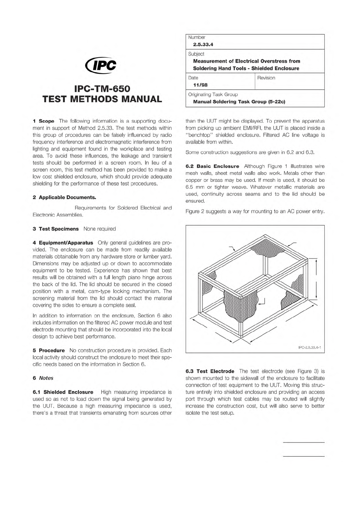
6.2
Basic
Enclosure
Although
Figure
1
illustrates
wire
mesh
walls,
sheet
metal
walls
also
work.
Metals
other
than
copper
or
brass
may
be
used.
If
mesh
is
used,
it
should
be
6.5
mm
or
tighter
weave.
Whatever
metallic
materials
are
used,
continuity
across
seams
and
to
the
lid
should
be
ensured.
Figure
2
suggests
a
way
for
mounting
to
an
AC
power
entry.
6.3
Test
Electrode
The
test
electrode
(see
Figure
3)
is
shown
mounted
to
the
sidewall
of
the
enclosure
to
facilitate
connection
of
test
equipment
to
the
UUT.
Moving
this
struc¬
ture
entirely
into
shielded
enclosure
and
providing
an
access
port
through
which
test
cables
may
be
routed
will
slightly
increase
the
construction
cost,
but
will
also
serve
to
better
isolate
the
test
setup.
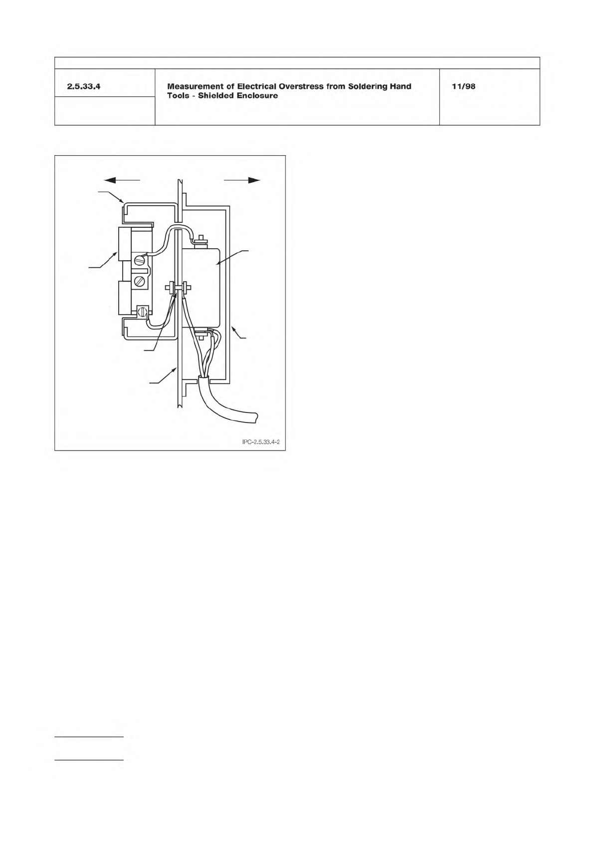
Figure 2 AC Power Entry Mounting Suggestion
Junction
Box
Duplex
Receptacle
Ground
Fastener
Enclosure
Wall
Metal
Cover
Line
Filter
AC Line
Cord
Inside Outside
IPC-TM-650
Number
Subject Date
Revision
Page 2 of 3
2.5.33.4
Measurement
of
Electrical
Overstress
from
Soldering
Hand
Tools
-
Shielded
Enclosure
11/98
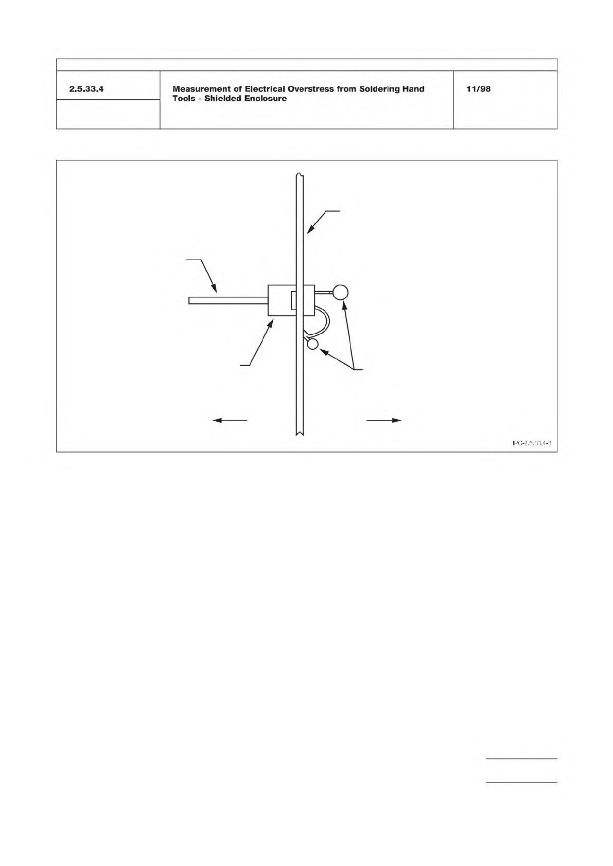
Figure 3 Test Electrode Mounting Suggestion
METAL
ENCLOSURE WALL
WIRE LOOPS
TO CONNECT SCOPE
PROBE AND GROUND CLIPS
OutsideInside
TEST
ELECTRODE
BOARD
DUAL READOUT
PANEL MOUNT
EDGE CARD CONNECTOR
IPC-TM-650
Number
Subject Date
Revision
Page 3 of 3