IPC-TM-650 EN 2022 试验方法--.pdf - 第606页
Figure 2 TDR Tr ace for a T ypi cal Cable Figure 3 Sample Cable Hanger IPC-TM-650 Number Subject Date Revision Page 2 of 4 2.5.18 Characteristic Impedance Flat Cables (Unbalanced) 7/84 B I PC-2-5-1 8-5 4.1 In this test, …
3.4.2
Measure the flexible base dielectric thickness and the
metal thickness of the twelve specimens by micrometer, cali-
per or similar following the stabilization period in 3.4.1. Nomi-
nal metal thickness to be tested is either 1 oz or 34.3 µm
[1350 µin] thick (preferred) or
1
⁄
2
oz or 17.1 µm [680 µin] thick.
3.4.3
On the specimens stabilized in 3.4.1, measure and
verify that the conductor widths are 3.2 mm ± 0.15 mm
[0.126 in ± 5.9 µin].
3.4.4
Examine the twelve specimens measured in 3.4.3
using normal or corrected 20/20 (also termed 6/6 or 1.0)
vision, and discard any peel strips showing the presence of
any wrinkles, cracks, blisters, or loose conductors. Twelve
specimens are required for the test, so any specimens not
meeting this criterion
be replaced.
3.4.5
Per IPC-TM-650, TM 2.4.13, Method B, subject the
specimens examined in 3.4.4 to pre-drying and then solder
float.
3.4.6
Examine the specimens subjected to solder float in
3.4.5 using normal or corrected 20/20 (also termed 6/6 or 1.0)
vision. Discard any peel strips showing the presence of any
wrinkles, cracks, blisters, or loose conductors. Verify that at
least twelve good specimens remain.
3.4.7
Place six specimens into an air-circulating oven at the
desired Service Temperature value. The oven temperature
be held at a tolerance of ± 3°C [5.4 °F]. The specimens
are to continuously remain in the oven for 1000 hours, -0
hours / +12 hours.
3.4.8
After being aged per 3.4.7, the test specimens
be cooled to room temperature at standard ambient labora-
tory conditions. After being cooled to room temperature, the
thermally aged (oven conditioned) specimens
be sub-
jected to a stabilization period of a minimum of 24 hours at
23 °C ± 2 °C [73.4 °F ± 3.6 °F] and 50% ± 5% RH.
3.4.9
After the stabilization period in 3.4.8, examine the
specimens using normal or corrected 20/20 (also termed 6/6
or 1.0) vision, and record the presence of any wrinkles,
cracks, blisters, or loose conductors, or any delamination.
3.5 Measurement of Peel Strength
3.5.1
AABUS, test specimens may have rigid reinforcement
material attached to all twelve specimens that were subjected
to the solder float in 3.4.5, including those six specimens that
were additionally subjected to thermal aging in 3.4.7. The rigid
reinforcement material
be attached prior to condi-
tioning and aging. The attachment of the rigid reinforcement
material depends on a number of factors, including the type of
peel test apparatus as described in IPC-TM-650, Method
2.4.9. If the rigid reinforcement material is to be utilized, it
should be adhered to the specimens using double-faced
adhesive tape or appropriate adhesive system to the back
side of the specimens.
If the test specimens are generated from double-clad flexible
base materials with metal remaining on the non-test side, the
additional rigid reinforcement material is unnecessary and
should not be used.
3.5.2
Measure the peel strength of the twelve conductors
per the procedures outlined in IPC TM-650, Method 2.4.9.
Specifically, peel the etched copper conductors away from
the dielectric at a 90° angle and at a 50.8 mm [2 in] per min-
ute crosshead speed.
3.6 Document and Report Results
3.6.1
Calculate the average peel strength of the six speci-
mens that were only exposed to the solder float (i.e., only as
per 3.4.5 and
exposed to the thermal aging of 3.4.7). Do
the same for the six thermally aged specimens per 3.4.7. Cal-
culate the ratio of the ‘‘thermally aged’’ average peel
strengths divided by the solder-floated only average peel
strength to determine the percentage retention of peel
strength. Record this number to ± 1% accuracy.
[Ave. of Six (6) Peel Strengths of Thermally Aged Specimens]
[Ave. of Six (6) Peel Strengths of Solder Floated-Only Specimens
x 100 = % of Peel Strength Retained
IPC-2-6-21-2
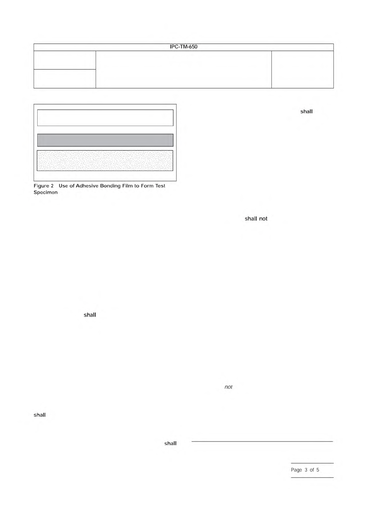
1 oz ED or RA Copper Foil Test Surface
(Shiny side toward the adhesive)
1 oz ED Copper Foil with Treated Matte
Side Inward as Support Material
Adhesive Bonding Film
Number
2.6.21
Subject
Service Temperature of Metal-Clad Flexible Laminate, Cover
Material and Adhesive Bonding Films
Date
6/11
Revision
B
IPC-TM-650
Figure
2
Use
of
Adhesive
Bonding
Film
to
Form
Test
Specimen
shall
not
shall
shall
shall
Page
3
of
5
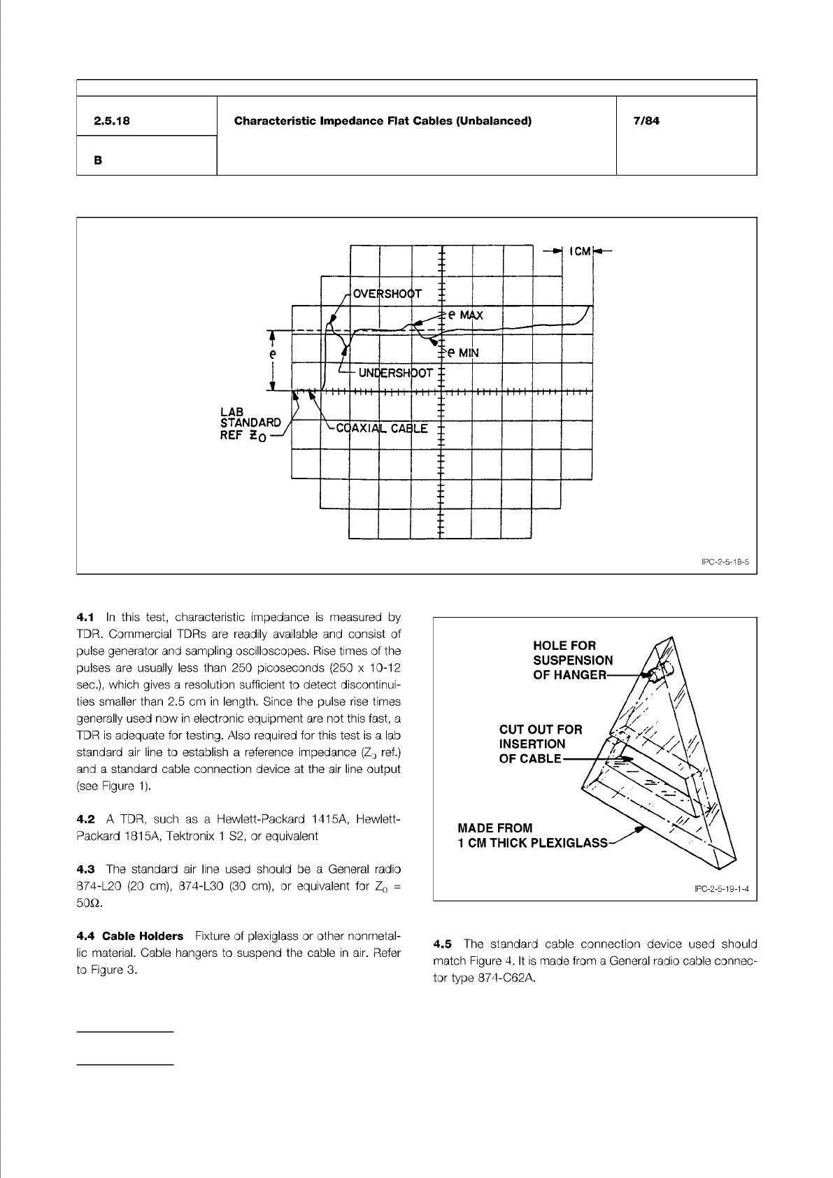
Figure 2 TDR Trace for a Typical Cable
Figure 3 Sample Cable Hanger
IPC-TM-650
Number
Subject Date
Revision
Page 2 of 4
2.5.18
Characteristic
Impedance
Flat
Cables
(Unbalanced)
7/84
B
I
PC-2-5-1
8-5
4.1
In
this
test,
characteristic
impedance
is
measured
by
TDR.
Commercial
TDRs
are
readily
available
and
consist
of
pulse
generator
and
sampling
oscilloscopes.
Rise
times
of
the
pulses
are
usually
less
than
250
picoseconds
(250
x
10-12
sec.),
which
gives
a
resolution
sufficient
to
detect
discontinui¬
ties
smaller
than
2.5
cm
in
length.
Since
the
pulse
rise
times
generally
used
now
in
electronic
equipment
are
not
this
fast,
a
TDR
is
adequate
for
testing.
Also
required
for
this
test
is
a
lab
standard
air
line
to
establish
a
reference
impedance
(Zo
ref.)
and
a
standard
cable
connection
device
at
the
air
line
output
(see
Figure
1).
4.2
A
TDR,
such
as
a
Hewlett-Packard
1415A,
Hewlett-
Packard
1815A,
Tektronix
1
S2,
or
equivalent
4.3
The
standard
air
line
used
should
be
a
General
radio
874-L20
(20
cm),
874-L30
(30
cm),
or
equivalent
for
Zo
二
50Q.
4.4
Cable
Holders
Fixture
of
plexiglass
or
other
nonmetal-
lic
material.
Cable
hangers
to
suspend
the
cable
in
air.
Refer
to
Figure
3.
4.5
The
standard
cable
connection
device
used
should
match
Figure
4.
It
is
made
from
a
General
radio
cable
connec¬
tor
type
874-C62A.
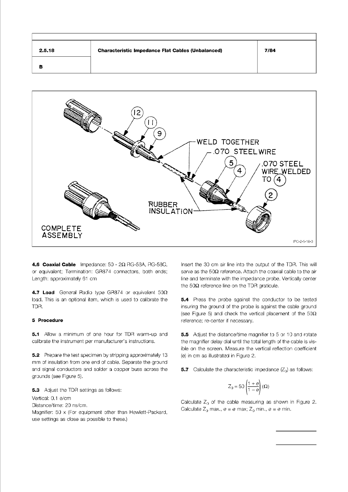
Figure 4 Cable Connection Device. Refer circled items to parts list. Made from General Radio Co. Type 874-C62A.
IPC-TM-650
Number
Subject Date
Revision
Page 3 of 4
2.5.18
Characteristic
Impedance
Flat
Cables
(Unbalanced)
7/84
B
4.6
Coaxial
Cable
Impedance:
50
-
2c
RG-58A,
RG-58C,
or
equivalent;
Termination:
GR874
connectors,
both
ends;
Length:
approximately
61
cm
4.7
Load
General
Radio
type
GR874
or
equivalent
50Q
load.
This
is
an
optional
item,
which
is
used
to
calibrate
the
TDR.
5
Procedure
5.1
Allow
a
minimum
of
one
hour
for
TDR
warm-up
and
calibrate
the
instrument
per
manufacturer's
instructions.
5.2
Prepare
the
test
specimen
by
stripping
approximately
1
3
mm
of
insulation
from
one
end
of
cable.
Separate
the
ground
and
signal
conductors
and
solder
a
copper
buss
across
the
grounds
(see
Figure
5).
5.3
Adjust
the
TDR
settings
as
follows:
Vertical:
0.1
e/cm
Distance/time:
20
ns/cm.
Magnifier:
50
x
(For
equipment
other
than
Hewlett-Packard,
use
settings
as
close
as
possible
to
these.)
Insert
the
30
cm
air
line
into
the
output
of
the
TDR.
This
will
serve
as
the
50Q
reference.
Attach
the
coaxial
cable
to
the
air
line
and
terminate
with
the
impedance
probe.
Vertically
center
the
50Q
reference
line
on
the
TDR
graticule.
5.4
Press
the
probe
against
the
conductor
to
be
tested
insuring
the
ground
of
the
probe
is
against
the
cable
ground
(see
Figure
5)
and
check
the
vertical
placement
of
the
50Q
reference;
re-center
if
necessary.
5.5
Adjust
the
distance/time
magnifier
to
5
or
10
and
rotate
the
magnifier
delay
dial
until
the
total
length
of
the
cable
is
vis¬
ible
on
the
screen.
Measure
the
vertical
reflection
coefficient
(e)
in
cm
as
illustrated
in
Figure
2.
5.7
Calculate
the
characteristic
impedance
(Zo)
as
follows:
1
+
Q
Zo
=
5O
宙
(
Q)
i
y
Calculate
Zo
of
the
cable
measuring
as
shown
in
Figure
2.
Calculate
Zo
max.,
e
=
e
max;
Zo
min.,
e
=
e
min.