IPC-TM-650 EN 2022 试验方法--.pdf - 第268页
Note: The Institute for Int erconnecting and Packaging E lectronic Circuits 2215 S anders Road • Northbrook, IL 60062-6135 Material in this T est M ethods Manual was voluntarily establis hed by T echni cal Committees of …
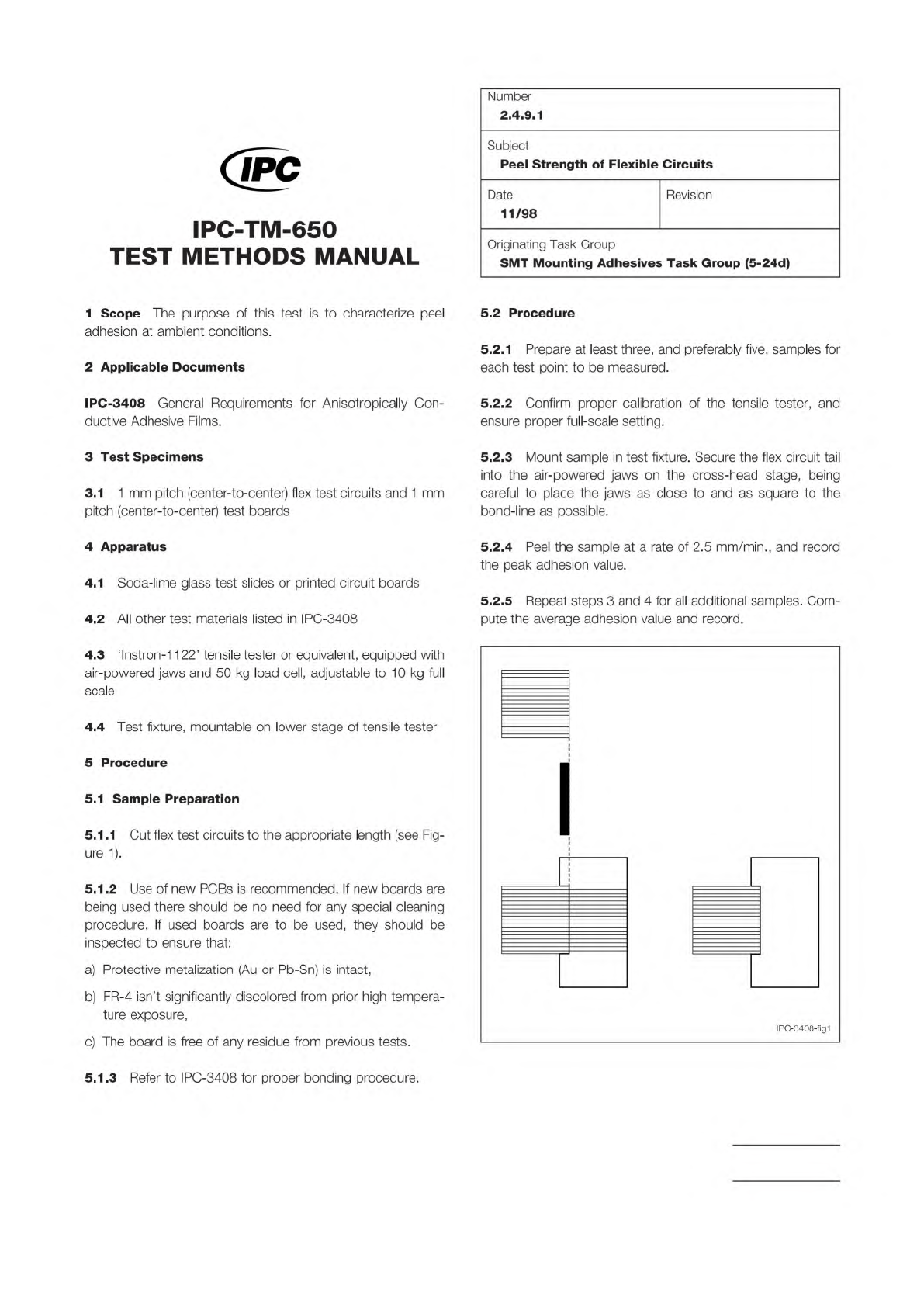
Figure 1 Sample Pattern
1 mm Pitch Flex, 17 traces
20 mm x 20 mm
ACF, 0.050 mm, 3.2 mm x 20 mm
a) Flex-Board b) Flex-Glass
The Institute for Interconnecting and Packaging Electronic Circuits
2215 Sanders Road • Northbrook, IL 60062-6135
Material in this Test Methods Manual was voluntarily established by Technical Committees of the IPC. This material is advisory only
and its use or adaptation is entirely voluntary. IPC disclaims all liability of any kind as to the use, application, or adaptation of this
material. Users are also wholly responsible for protecting themselves against all claims or liabilities for patent infringement.
Equipment referenced is for the convenience of the user and does not imply endorsement by the IPC.
Page 1 of 1
IPC-TM-650
TEST
METHODS
MANUAL
1
Scope
The
purpose
of
this
test
is
to
characterize
peel
adhesion
at
ambient
conditions.
2
Applicable
Documents
IPC-3408
General
Requirements
for
Anisotropically
Con¬
ductive
Adhesive
Films.
3
Test
Specimens
3.1
1
mm
pitch
(center-to-center)
flex
test
circuits
and
1
mm
pitch
(center-to-center)
test
boards
4
Apparatus
4.1
Soda-lime
glass
test
slides
or
printed
circuit
boards
4.2
All
other
test
materials
listed
in
IPC-3408
4.3
1nstron-1
1
22'
tensile
tester
or
equivalent,
equipped
with
air-powered
jaws
and
50
kg
load
cell,
adjustable
to
1
0
kg
full
scale
4.4
Test
fixture,
mountable
on
lower
stage
of
tensile
tester
5
Procedure
5.1
Sample
Preparation
5.1.1
Cut
flex
test
circuits
to
the
appropriate
length
(see
Fig¬
ure
1).
5.1.2
Use
of
new
PCBs
is
recommended.
If
new
boards
are
being
used
there
should
be
no
need
for
any
special
cleaning
procedure.
If
used
boards
are
to
be
used,
they
should
be
inspected
to
ensure
that:
a)
Protective
metalization
(Au
or
Pb-Sn)
is
intact,
b)
FR-4
isn't
significantly
discolored
from
prior
high
tempera¬
ture
exposure,
c)
The
board
is
free
of
any
residue
from
previous
tests.
Number
2.4.9.1
Subject
Peel
Strength
of
Flexible
Circuits
Date
11/98
Revision
Originating
Task
Group
SMT
Mounting
Adhesives
Task
Group
(5-24d)
5.2
Procedure
5.2.1
Prepare
at
least
three,
and
preferably
five,
samples
for
each
test
point
to
be
measured.
5.2.2
Confirm
proper
calibration
of
the
tensile
tester,
and
ensure
proper
full-scale
setting.
5.2.3
Mount
sample
in
test
fixture.
Secure
the
flex
circuit
tail
into
the
air-powered
jaws
on
the
cross-head
stage,
being
careful
to
place
the
jaws
as
close
to
and
as
square
to
the
bond-line
as
possible.
5.2.4
Peel
the
sample
at
a
rate
of
2.5
mm/min.,
and
record
the
peak
adhesion
value.
5.2.5
Repeat
steps
3
and
4
for
all
additional
samples.
Com¬
pute
the
average
adhesion
value
and
record.
5.1.3
Refer
to
IPC-3408
for
proper
bonding
procedure.
Note:
The Institute for Interconnecting and Packaging Electronic Circuits
2215 Sanders Road • Northbrook, IL 60062-6135
Material in this Test Methods Manual was voluntarily established by Technical Committees of the IPC. This material is advisory only
and its use or adaptation is entirely voluntary. IPC disclaims all liability of any kind as to the use, application, or adaptation of this
material. Users are also wholly responsible for protecting themselves against all claims or liabilities for patent infringement.
Equipment referenced is for the convenience of the user and does not imply endorsement by the IPC.
Page 1 of 2
IPC-TM-650
TEST
METHODS
MANUAL
1
Scope
In
order
to
assess
the
actual
performance
of
any
given
lot
of
material,
it
is
necessary
to
apply
and
thermally
bond
the
material
between
the
substrates
of
interest.
This
method
describes
the
recommended
procedure
for
both
pre¬
tacking
and
bonding
anisotropically
conductive
films
(ACF).
This
method
describes
a
fully
manual
procedure.
2
Applicable
Documents
3
Test
Specimens
3.1
Appropriate
flex
circuit
and
test
substrate(s)
4
Apparatus
4.1
"Hot-Bar”
type
soldering
station:
Unitek
PM-4
or
equivalent
4.2
Thermode:
1
.5
mm
width
minimum;
sufficient
length
to
span
bond-line
4.3
Hot-Plate:
Pace,
Inc.,
'Hot
Spot'
or
equivalent
(optional
if
hot
bar
bonder
is
used
for
tacking
or
if
adhesive
can
be
tacked
without
applied
heat)
4.4
Razor
blade
4.5
Cotton
swab
(optional;
see
4.3)
4.6
One
roll
or
sheet
of
conductive
adhesive
4.7
Appropriate
compliant
material
(as
required)
5
Procedure
5.1
Sample
Preparation
5.1.1
Allow
the
roll
of
adhesive
to
equilibrate
at
room
tem¬
perature
before
handling.
5.1.2
Cut
the
flex
circuit
sample
to
the
appropriate
length
and
width
for
the
given
performance
test.
5.1.3
Cut
an
adhesive
sample
to
match
the
width
and
length
of
the
bond
area.
Number
2.4.9.2
Subject
Bonding
Process
Date
Revision
11/98
Originating
Task
Group
SMT
Mounting
Adhesives
Task
Group
(5-24d)
5.2
Procedure
5.2.1
Position
the
adhesive
over
the
pads
on
the
flex
circuit,
liner-side
up.
5.2.2
If
the
adhesive
requires
heat
to
tack
it,
tack
the
adhe¬
sive
in
place
on
the
flex
circuit
using
the
hot
plate
and
cotton
swab
(alternatively,
the
adhesive
can
be
tacked
using
an
appropriately
low
setting
of
the
hot
bar
equipment).
The
adhe¬
sive
should
be
easily
tackable
with
a
three
to
five
second
exposure
at
1
00℃.
A
cotton
swab
should
be
used
to
apply
mild
pressure
in
order
to
facilitate
wetting.
Allow
the
flex
circuit
to
cool
before
handling
further.
5.2.3
Peel
the
release
liner
away
from
the
flex
circuit
in
order
to
expose
the
adhesive.
The
adhesive
may
need
pre-cutting
(using
a
razor
blade)
to
separate
it
from
the
liner
along
the
starting
edge.
5.2.4
Align
the
flex
circuit
to
the
test
substrate.
In
instances
requiring
extreme
accuracy
of
alignment,
it
is
helpful
to
affix
the
flex
circuit
relative
to
the
substrate
to
prevent
misregistra¬
tion
prior
to
and
during
bonding.
This
can
be
accomplished
with
custom
fixturing.
Alternatively,
a
soldering
iron
can
be
brushed
lightly
along
the
bond-line
in
order
to
tackify
the
adhesive,
thereby
temporarily
adhering
the
flex
circuit
to
the
test
substrate.
When
a
soldering
iron
is
used,
it
should
be
powered
through
a
Variac
in
order
to
provide
temperature
control.
The
temperature/time
of
the
soldering
iron
should
be
just
high
enough
to
tackify
the
adhesive
but
not
so
high
as
to
substan¬
tially
cross-link
the
adhesive
(i.e.,
100°-130℃)
and
only
a
few
seconds
exposure
to
these
temperatures.
5.2.5
Bond
the
flex
circuit
to
the
test
substrate
using
the
hot-bar
soldering
station.
Apply
a
minimum
of
20
kg
and
a
maximum
of
40kg/sq.
cm
of
total
bond-line
area
(or
as
recom¬
mended
by
the
adhesive
vendor),
then
ramp
the
temperature
to
the
set
point.
The
thermode
set
point
needs
to
be
set
to
permit
the
adhesive
layer
to
reach
1
80℃
within
1
0
seconds
(or
as
recommended
by
the
adhesive
vendor)
of
the
time
at
which
the
thermode
reaches
its
setpoint.
The
thermode
should
remain
at
the
setpoint
for
a
time
sufficient
to
cure
the
adhesive
according
to
vendor's
specification
(typically
20
sec¬
onds).
Some
vendors
may
advise
that
the
bond
pressure

IPC-TM-650
Number
Subject Date
Revision
Page 2 of 2
2.4.9.2
Bonding
Process
11/98
should
be
maintained
until
the
adhesive
layer
cools
to
100℃.
Allow
the
test
sample
to
cool
slightly
before
handling.
The
compliant
material
(if
one
is
used)
should
be
placed
between
the
thermode
and
flex
circuit
prior
to
bonding.