IPC-TM-650 EN 2022 试验方法--.pdf - 第512页
The t ransfer st andard have precision coax connec tors that match the test cables and probes. T he uncertainty in the nominal characteristic impedance of the transfer standards be less than or equal to ± 0.015 Z ref , w…
the connector. Table 4-3 provides the typical connector
torque specifications.
4.3.2 Cabling
All test cables be high-quality, low-
phase delay coax and with a nominal characteristic imped-
ance of 50 Ω. Cables used in the measurement circuit of the
transmission line under test
have connectors that are
compatible with the instrument and probes. The bandwidth of
the cable must be great enough so that the cable does not
limit the accuracy of the propagation delay measurement. The
length of the cables should be kept to a minimum. The total
insertion loss (including connector loss) of the cabling con-
necting the transmission line under test to the TDR should be
kept to less than 3.3 dB/m (1db/foot) at 26.5 GHz. Table 4-4
contains suggested maximum cable lengths for the TDR test
set up as depicted in Figure 5-1 and described in 5.2.
4.3.3 Probes
The probe assembly characteristic imped-
ance
either be 50 Ω or the same value as the charac-
teristic impedance of the transmission line under test, with an
uncertainty of ± 1.0 Ω or less. The probe tips should be of
sufficient diameter and pitch (spacing between signal and
ground tips) to provide accurate and repeatable connections
to the desired probe contact pad geometry (see IPC-2141 for
additional recommendations on probe landing layouts for TDR
coupons). Single-ended probes should contain two electrode
tips, one each for the signal and ground lines. The probe tips
should have moderately sharp edges to cut through any
oxides. The probe bandwidth should be sufficient for the
desired temporal/spatial resolution (see 4.1.2). The probe
response time should be sufficiently short so as not to
increase the duration of the measurement period. The overall
performance of the probe can be incorporated into the TDR
system response for computing TDR system temporal/spatial
resolution (see 4.1.2). Inconsistent probe force and placement
is common and can cause a significant yet unknown error in
t
d
. Probe connections to the measurement system cables
should be tightened with a torque wrench following the con-
nector specifications. For hand held probe assemblies, the
probe handle should be ergonomically shaped.
4.3.4 Terminations
TDR sources are not perfect voltage
source generators; they may perform differently under differ-
ent electrical load conditions. Therefore, the termination con-
ditions of any verification experiments should match those of
the interconnection test structures, and all test structures in a
given specimen should be of the same design. For example, if
the propagation delay test is to be performed on lines that are
electrically open at their far end, all lines should be terminated
in electrically open circuits, and any TDR field verification tests
(see 5.2.1.2) should be made using open circuit terminations.
4.3.5 ESD Protection
Static build up on specimens and
test cables prior to test can damage the signal samplers in the
TDR equipment; ESD protection and transmission line dis-
charging procedures must be used. ESD protection can be
supplied internally to the TDR system or externally using a
Static Isolation Unit (SIU). If supplied externally using a coaxial
switch (as shown in Figure 5-1), the switch should be placed
between the transmission line under test and the TDR instru-
mentation. The SIU should have a return loss and insertion
loss less than 16 dB and 0.3 dB, respectively, at 18 GHz. A
maximum of 30.0 cm [11.8 in] of high quality, high frequency
cable may be used to connect the TDR instrument to the SIU
protection switch. Test interconnections should be first
grounded with the SIU and/or passed through some type of
deionization device prior to testing to remove any residual
static electrical charge. Use of proper ESD control methods,
control components and humidity control will help reduce
electrostatic discharge damage to the measurement system.
Automation software can be used to enhance the effective-
ness of the static isolation unit by switching the static isolation
unit on/off as required to minimize the amount of time that the
TDR sampling unit is exposed to potential ESD.
4.3.6 Transfer Standard
The TDR measurement system
(see Figure 5-1) specified for measuring propagation delay
requires a precision coaxial transmission line to set the refer-
ence impedance of the reflectometer measurements. This
standard
be a rigid, or semi-rigid, cable not more than
10 cm long with a uniform impedance profile along its length.
[The conversion factor is 0.1128 N-m/(lb-in)]
SMA 0.56 N-m (5 lb-in)
3.5, 2.92, and 2.4 mm 0.90 N-m (8 lb-in)
Sampling Unit to Static
Isolation Unit
30.0 cm [11.8 in]
Static Isolation Unit to In-Line
Secondary Standard
91.0 cm [35.83 in]
Transfer Standard (such as
semi-rigid coaxial cable)
10.0 cm [3.94 in]
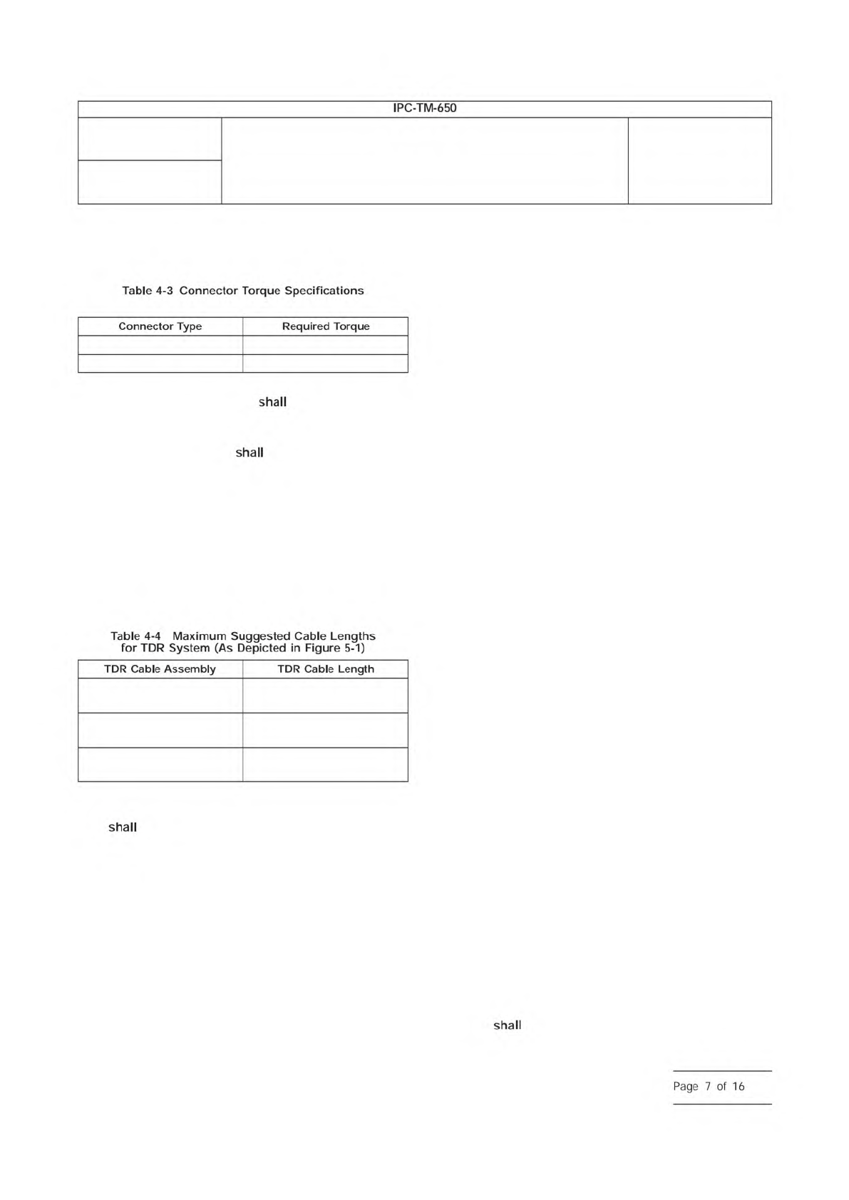
Number
2.5.5.11
Subject
Propagation Delay of Lines on Printed Boards by TDR
Date
04/2009
Revision
IPC-TM-650
―
Table
4-3
Connector
Torque
Specifications
Connector
Type
Required
Torque
Table
4-4
Maximum
Suggested
Cable
Lengths
for
TDR
System
(As
Depicted
in
Figure
5-1)
TDR
Cable
Assembly
TDR
Cable
Length
shall
Page
7
of
16
The transfer standard have precision coax connectors
that match the test cables and probes. The uncertainty in the
nominal characteristic impedance of the transfer standards
be less than or equal to ± 0.015 Z
ref
, where Z
ref
is the
characteristic impedance of the transfer standard (nominally
50 Ω.)
4.3.7 Check Standards
The method makes use of two
precision coaxial air lines of two different lengths to verify the
operation of a test set-up (see 5.2.1.2). The air lines are pre-
cision coaxial lines where the center conductors are held in
place with an isolation bead or the center pins of the end
connectors, and are not filled with any other dielectric mate-
rial. The coaxial air lines serve as a precise delay standard that
can be measured during field checks (see 5.2.1.2) to verify the
measurement set-up. The coaxial air line standards are avail-
able commercially with any of the precision coaxial connec-
tors. Probe contact to coaxial transitions must be fabricated
to use with a given probe tip configuration.
5 Procedures
In TDR, the observed voltage waveform is
the sum of incident and reflected signals. The reflections are
related to the difference between the characteristic imped-
ance Z
0
of a transmission line and any impedance discontinui-
ties along the transmission line or at its end.
The method procedures establish the means of determining a
time delay per unit length t
d
from TDR measurements of two
transmission lines that differ in length. The transmission lines
are the interconnect test structures fabricated in PB materials
as specified. The far end of the transmission line is either
electrically open- or short-circuited in order to create a clearly
observable reflection feature in the measured TDR waveform.
The procedures in this section establish the propagation delay
per unit length as the differential propagation time obtained
using the TDR measurements of two interconnect test lines
divided by the length of the same interconnects:
t
d
= t
p
/ 2L
p
Here, t
p
is the measured propagation time difference given by
t
p
=
?
t
T1
− t
T2
?
,
where t
T1
is the round-trip propagation time for the first trans-
mission line and t
T2
is the round-trip propagation time of the
second transmission line.
L
p
is the propagation length difference of the transmission line
pair given by
L
p
=
?
L
T1
− L
T2
?
,
where L
T1
is the length of the first transmission line and L
T2
is
the length of the second transmission line.
5.1 Measurement Preliminaries
This section provides
common considerations for the calibration and initial configu-
ration of the TDR measurement system, and the method to
establish the waveform epoch (time window) used in the delay
measurements (see 5.2 and 5.3).
5.1.1 System Calibrations
5.1.1.1 Manufacturer Calibrations
The TDR oscilloscope
or other TDR equipment used
be calibrated and ser-
viced following the recommended schedule of the instrument
manufacturers.
5.1.1.2 Field Calibrations
Manufacturer ecommended
field calibrations
be performed in addition to scheduled
factory calibrations. TDR system field calibrations
be
performed at the frequency recommended by the instrument
manufacturers and after a change of any system component,
such as a sampler of TDR source unit. The user must ensure
adequate system warm-up time before performing field cali-
brations, as specified by the instrument manufacturers.
Users-accessible field calibrations for TDR oscilloscopes may
include the application of an internal voltage calibration for
each sampler and TDR source. Though not required for this
method, TDR field calibrations may also include a reflection
coefficient or impedance normalization/calibration procedure
where standards are connected to the instrument’s test port
following a menu-driven procedure. Field calibrations are
required for the following reasons:
a. TDR instrument specifications vary with temperature
b. TDR instrument specifications vary with time (drift)
c. TDR instrument specifications vary due to minor ESD dam-
age
d. TDR instrument factory calibration usually does not include
user supplied auxiliary components (i.e., cables, probes,
etc.)
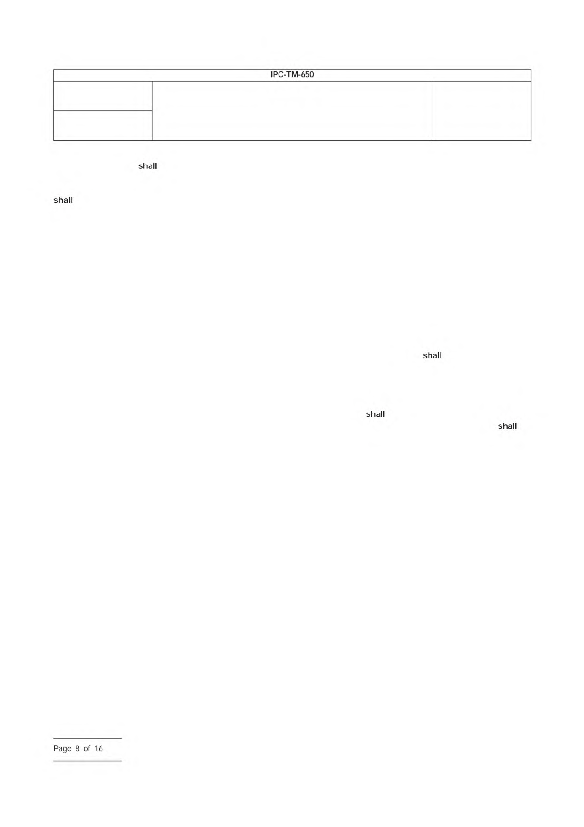
Number
2.5.5.11
Subject
Propagation Delay of Lines on Printed Boards by TDR
Date
04/2009
Revision
IPC-TM-650
shall
shall
shall
shall
Page
8
of
16
5.1.2 Pre-Measurement Checks
5.1.2.1 Instrument Warm-Up and Stability
Before per-
forming delay measurements, the user
ensure adequate
instrument warm-up time as specified by the instrument
manufacturers, and ensure that the TDR waveform is not drift-
ing in amplitude or time.
5.1.2.2 Environmental Conditions
The user ensure
that the temperature and humidity of the test environment is
within TDR instrument specifications and that the conditions
will be stable for the duration of the measurements. If the test
environment is substantially different than that used for speci-
men conditioning (see 3.3), the user document this in
the test reports.
5.1.2.3 Test Structure Isolation
The user ensure
that the signal line and reference planes of the test structures
are located an adequate distance from objects and surfaces
(such as the work surface of a test bench) that could electri-
cally couple or interact with the test structure and probes. If
surface layer microstrip lines are used, the recommendation is
to keep extraneous objects and surfaces at least 6 w from the
test coupon or PB, were w is the width of the signal line. If the
tests are being conducted with hand probes, care must be
taken to ensure that the hands and arms of the operator do
not come in close proximity to the coupon or PB being tested.
Any fixtures used to ensure electrical isolation of the test fix-
tures must also be sufficiently strong to accommodate the
probing force required for repeatable electrical connections.
5.1.3 Suitable Waveform Epochs
The waveform epoch is
the measurement interval over which the propagation time for
a given discontinuity will be computed. The time epoch may
be described in terms of the TDR instrument parameters delay
and time per division. The user
ensure that the instru-
ment settings can be adjusted so the waveform epochs can
contain the arrival of the far end reflection signals of both the
shorter line and the longer line in the test structure; the user
must ensure an epoch includes the reflection signal and suffi-
cient pre- and post-waveform data to establish the required
reference amplitude levels; and the user
ensure that the
delay and time/div settings can re-adjusted to repeat the
desired epochs. This requires probing both test structures
using the TDR measurement set-up (similar to that depicted in
Figure 5-1). As shown in Figure 5-1, the user may first find the
arrival point of the reflection signal for the open-circuit probe
to help locate the subsequent reflection signal of the intercon-
nection test structure.
5.1.4 Suitable Amplitude Resolution
In order to com-
pute propagation delay, this method requires the recording of
the instants when the TDR waveform crosses a specified volt-
age reference level. The reference level, V
REF
, is given gener-
ally by:
V
REF
= xV
refl
+ V
off,refl
where V
refi
is the amplitude of the reflected pulse (measured
when it is superimposed on an incident step pulse), x is the
fraction of V
refl
used to determine the transition instant (for
example, x = 0.5 corresponds to the 50% reflection amplitude
value), and V
off, refl
is the amplitude of an incident TDR step
pulse.
This method specifies two possible values for x:
x
5%
= 0.05
x
50%
= 0.50
The method also allows the user to specify their own x as long
as the same value of x is used in all delay measurements and
verification field tests. The user must document which value of
x is used in the test reports.
The user
ensure that the TDR equipment amplitude set-
tings can be adjusted to capture the reference level V
REF
with
sufficient resolution to minimize errors in recording time of the
crossing instant.
5.2 Propagation Delay TDR Measurement Procedures
This section contains the methods for measuring the propa-
gation delay of single-ended transmission lines. The following
steps should be used when the interconnect test structures
under test are unbalanced (single-ended) transmission lines.
This process can be followed or automated (recommended).
Additionally, the use of quality fixtures based or robotic prob-
ing systems may reduce probe placement uncertainty com-
pared to hand probe techniques of certain users.
5.2.1 Multiple Line Method
To mitigate the effects of
imperfect measurement system cables, probes, and contact
pad discontinuities, the propagation delay measurements are
defined using the ratio of differences of two measurements
made on separate lines that are very similar except for their
physical length. Therefore, the procedure requires careful and
repeatable connections and measurements of TDR waveform
from two lines of the interconnection test structure.
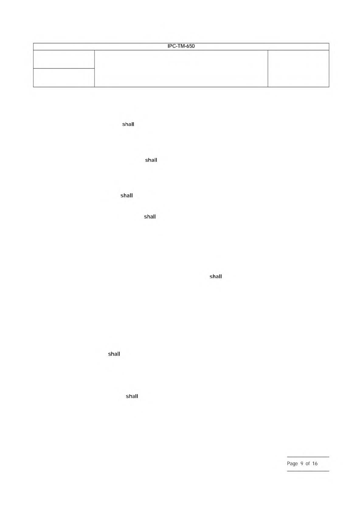
Number
2.5.5.11
Subject
Propagation Delay of Lines on Printed Boards by TDR
Date
04/2009
Revision
IPC-TM-650
shall
shall
shall
shall
shall
shall
Page
9
of
16