IPC-TM-650 EN 2022 试验方法--.pdf - 第628页
3.1 Coupon Design R ules Certain d esigns rules mu st be applied to achieve thermal uniformity. Electronic design files for co upon c onstr uction ar e avail able from the e quipment supplier or printed board supplier. T…
Test Procedure Pass/Fail Criteria Value Recorded Status
Ground Measurements (2.5.33.1) 5 [ Pass [ Fail
Transient Measurements/Pass 1 (2.5.33.2)
2 V peak V [ Pass [ Fail
Transient Measurements/Pass 2 (2.5.33.2)
2 V peak V [ Pass [ Fail
Transient Measurements/Pass 3 (2.5.33.2)
2 V peak V [ Pass [ Fail
Current Leakage Measurements (2.5.33.3)
1.0 µ-amp DC µ-amp DC [ Pass [ Fail
Current Leakage Measurements (2.5.33.3) 1.0 µ-amp ACrms µ-amp ACrms [ Pass [ Fail
Equipment Function Brand Model Calibration Date
AC millivoltmeter true mvAC/rms
DC millivoltmeter 60 mv DC
Ohmmeter resistances beyond 5
M
Storage Oscilloscope 100 Mhz bandwidth or
faster, 1 M
input
vertical amplifier
Constant Current Source 10 milliamps DC
Equipment Scale Used Cal / Std Meas. Baseline Meas.
AC millivoltmeter
DC millivoltmeter
Ohmmeter
Storage Oscilloscope
Constant Current Source
NAME: DATE:
COMPANY: PHONE:
IPC-TM-650
Number
Subject Date
Revision
Page 4 of 5
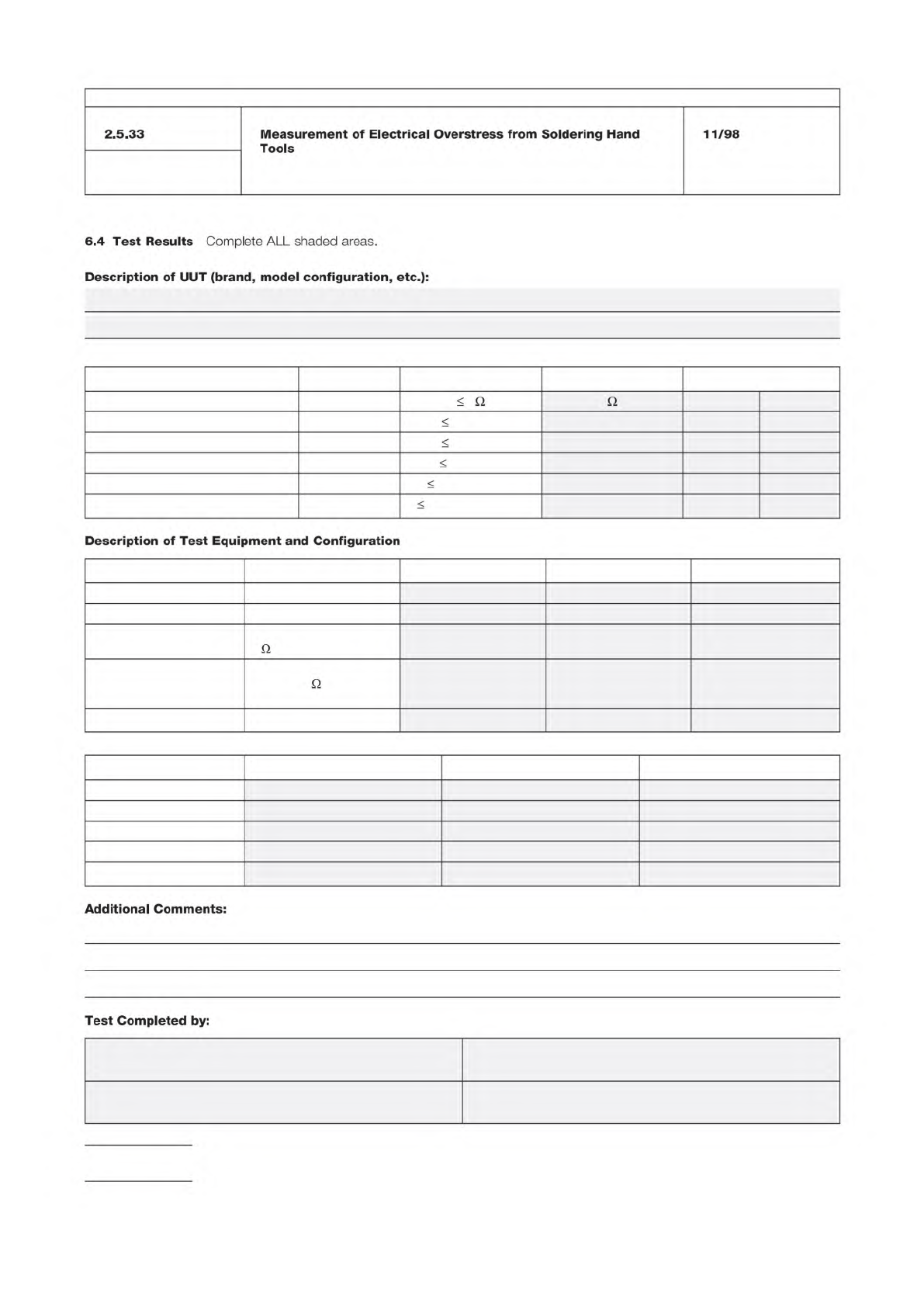
2.5.33
Measurement
of
Electrical
Overstress
from
Soldering
Hand
Tools
11/98
6.4
Test
Results
Complete
ALL
shaded
areas.
Description
of
UUT
(brand,
model
configuration,
etc.):
Q Q
Description
of
Test
Equipment
and
Configuration
Q
Q
Additional
Comments:
Test
Completed
by:
3.1 Coupon Design Rules
Certain designs rules must be
applied to achieve thermal uniformity. Electronic design files
for coupon construction are available from the equipment
supplier or printed board supplier. The resistance values (volt-
age drops) for each coupon are monitored independently for
each electrical net in test, using a four wire measurement
technique.
The test coupon(s) is incorporated on the panel to monitor or
qualify design, materials, or processes of product and/or reli-
ability assurance.
4 Apparatus or Material
At the time of publication of this
test method, 4.1 and 4.2 list the only known equipment
manufacturers of this test equipment. Equivalent test systems
may be used that operate on principles similar to those iden-
tified in Method A or B. IPC encourages their submission
along with relevant validation test data. This test method will
be revised as necessary to include these test systems as this
information becomes available.
Validation of this test method was performed with the equip-
ment listed in 4.1 and 4.2. Test conditions for the validation
are provided in 6.5. If alternate test equipment is used, valida-
tion in accordance with IPC-MDP-650 and 6.5 is recom-
mended.
4.1 Method A
4.1.1
This equipment is available from:
PWB Interconnect Solutions Inc. (Canada)
URL: www.pwbcorp.com
Equipment Type: IST
4.1.2
Two (2) four-pin, 2.54 mm [0.1 in] male connector
(ITW Pancon MFSS100-4-D or equivalent).
4.1.3
Sn60Pb40, Sn63Pb37, or lead free solder.
4.1.4
Solder flux.
4.1.5
Soldering iron.
4.2 Method B
4.2.1
This equipment is available from:
i3 Electronics (USA)
(formerly Endicott Interconnect Technologies)
URL: www.i3electronics.com
Equipment Type: CITC, CITC-TCR
4.2.2
4-wire multimeter, capable of measuring milliohms
4.2.3
Thermal imaging equipment – optional
5 Procedures
5.1 Sample Selection
5.1.1
Bench top measure the resistance of each net of the
coupon with a 4-wire multimeter. A net with an open cannot
be tested. A net with a short must be reworked to test the
coupon.
5.1.2 Coupon Selection
Select coupons for evaluation
based upon the test required as described in 5.1.2.1 through
5.1.2.3.
5.1.2.1 Random Sampling
A sample chosen without
regard to any characteristic of the individual coupons within a
population, within one or more lots.
5.1.2.2 Selective Sampling
A sample chosen based on
the resistance measurements of the sense and power nets.
Testing may include high, midrange and low resistance mea-
surements.
5.1.2.3 Comparative Sampling
A sample chosen based
on the resistance measurements of the sense and power
nets. Testing should include similar resistance measurements
for the populations being tested.
5.2 Method A Procedure
5.2.1 Single Sense Testing
Solder two four-pin male con-
nectors in the 1.02 mm [0.040 in] holes at the left and right
edges of the coupon (see Figure 3-1). A solder fillet must be
apparent on both sides of the coupon.
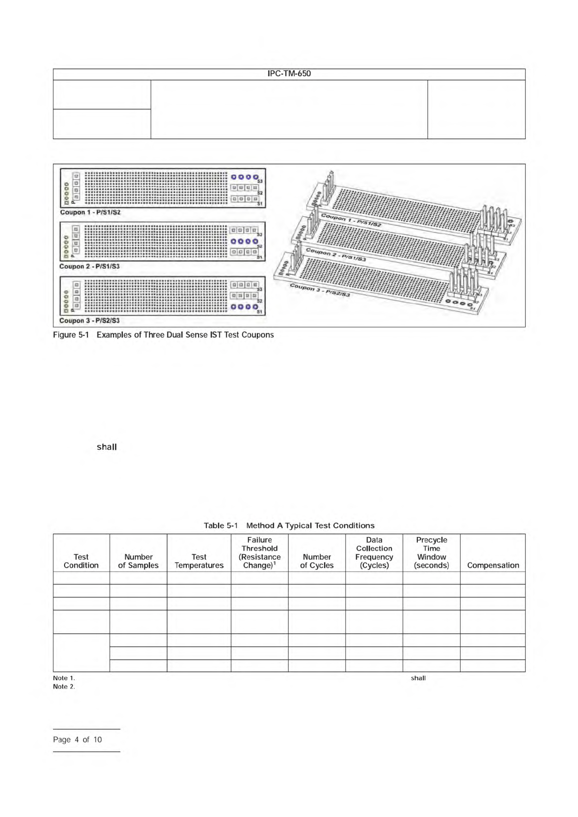
5.2.1.1 Dual Sense Testing (Optional)
When Dual Sense
Testing is required, solder three four-pin male connectors in
the 1.02 mm [0.040 in] holes at the edges of the coupon (see
Figure 5-1). A solder fillet must be apparent on both sides of
the coupon.
Dual Sense coupons may be tested using the Single
Sense Testing method.
Number
2.6.26
Subject
DC Current Induced Thermal Cycling Test
Date
5/14
Revision
A
IPC-TM-650
NOTE:
Page
3
of
10
5.2.2
Position the coupons at each test head by attaching
male to female connectors.
5.2.3 Baseline Performance (Optional)
Establish a per-
formance baseline by completing two Method A cycles and
then stop the test at the end of the cooling cycle.
5.2.4 Capacitance Test (Optional)
If required, the capaci-
tance test
be performed per IPC-TM-650, Method
2.5.35.
5.2.5 Assembly Precondition (Optional)
Assembly pre-
conditioning is recommended to simulate the assembly envi-
ronment to which the printed boards are exposed (see 6.1).
5.2.6
Unless otherwise specified by the user, test all via
types and materials per the default test condition in accor-
dance with Table 5-1. For testing of samples containing
microvia structures, use the microvia test condition. For test-
ing of samples containing polyimide materials, use the polyim-
ide test condition.
5.2.7 Pre-Cycling Test Sequence
The following para-
graphs detail the sequence for a single coupon, however this
sequence is done at all test heads simultaneously. The ambi-
ent resistance, resistance at test temperature, rejection resis-
tance, and current are calculated for each coupon and dis-
played on the PC monitor.
IPC-2626-5-1
(Top-Down View as shown at left and Isometric View as shown at right)
Default 6 150 °C 10% 250 25 3 Calculated
Polyimide 6 AABUS 10% 250 25 3 Calculated
Microvias
2
6 190 °C 10% 250 25 3 None
Polyimide
Microvias
2
6 AABUS 10% 250 25 5 None
Survivability
Testing
6 230 °C 10% 10 1 5 None
6 245 °C 10% 10 1 5 None
6 260 °C 10% 10 1 5 None
For Dual Sense Testing, both the ‘‘Cycle Using’’ and the ‘‘Cycle Failing On’’ fields on the Method A test equipment be set to ‘both sense circuits.’
Power on the microvia or heating trace net.
Number
2.6.26
Subject
DC Current Induced Thermal Cycling Test
Date
5/14
Revision
A
IPC-TM-650
[0同可&
回叫
oooo
Coupon
1
-P/S1/S2
Coupon
2
-
P/S1/S3
Coupon
3
-
P/S2/S3
Figure
5-1
Examples
of
Three
Dual
Sense
1ST
Test
Coupons
shall
Table
5-1
Method
A
Typical
Test
Conditions
Note
1.
Note
2.
Test
Condition
Number
of
Samples
Test
Temperatures
Failure
Threshold
(Resistance
Change)1
Number
of
Cycles
Data
Collection
Frequency
(Cycles)
Precycle
Time
Window
(seconds)
Compensation
0000c
-n
p-d
O0O0D
d
OOOOQ
Page
4
of
10