IPC-TM-650 EN 2022 试验方法--.pdf - 第344页
The Institute for Int erconnecting and Packaging E lectronic Circuits 2215 S anders Road • Northbrook, IL 60062-6135 Material in this T est M ethods Manual was voluntarily establis hed by T echni cal Committees of the IP…
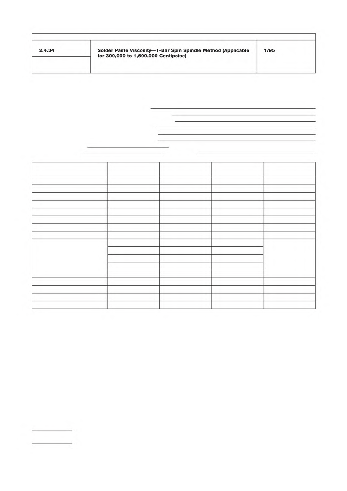
Table 1 Test Report on Solder Paste
Enter appropriate information in top portion of report and complete report by entering the test results or checkmarks in the appropriate spaces.
Inspection Purpose: QPL I.D. Number:
__ Qualification Manufacturer’s Identification:
__ Quality Conformance A Manufacturer’s Batch Number:
__ Quality Conformance B Date of Manufacture:
__ Shelf-Life Extension Original Use-By Date:
__ Performance Revised Use-By Date:
Date Inspection Completed: Overall Results: __ Pass __ Fail
Inspection Performed by:
Witnessed by:
Inspections
User’s Actual
Requirement Test Result P/F (*) Tested by & Date
Material
Visual
Metal Content
Viscosity
Solder Ball
Slump
Alloy
Flux
Powder Size
% In Top Screen
% In Next Screen
% In Bottom Screen
% In Receiver Bottom
Max. Powder Size
Powder Shape
Tack
Wetting
* P/F = PASS/FAIL; enter P if test results are within tolerance of actual requirement; otherwise, enter F
IPC-TM-650
Number
Subject Date
Revision
Page 2 of 2
2.4.34
Solder
Paste
Viscosity
―
T-Bar
Spin
Spindle
Method
(Applicable
for
300,000
to
1,600,000
Centipoise)
1/95
The Institute for Interconnecting and Packaging Electronic Circuits
2215 Sanders Road • Northbrook, IL 60062-6135
Material in this Test Methods Manual was voluntarily established by Technical Committees of the IPC. This material is advisory only
and its use or adaptation is entirely voluntary. IPC disclaims all liability of any kind as to the use, application, or adaptation of this
material. Users are also wholly responsible for protecting themselves against all claims or liabilities for patent infringement.
Equipment referenced is for the convenience of the user and does not imply endorsement by the IPC.
Page 1 of 2
IPC-TM-650
TEST
METHODS
MANUAL
1
.0
Scope
This
test
specifies
a
standard
procedure
for
determining
the
viscosity
of
solder
paste
in
the
range
of
50,000
to
300,000
centipoise.
2
.0
Applicable
Documents
None
3
.0
Test
Specimen
Paste
to
be
tested
shall
stabilize
at
25℃
±
1
℃
for
a
minimum
of
24
hours
prior
to
testing.
The
paste
volume
shall
be
sufficient
to
fill
a
test
container
having
a
minimum
diameter
of
5
cm
and
a
minimum
depth
of
5
cm.
4
.0
Equipment/Apparatus
Equipment
used
shall
be
a
spindle
type
viscometer
(Brookfield
RVTD
or
equivalent)
with
a
heli
path
stand
and
pen
recorder.
A
TC
spindle
shall
be
used
for
tests.
Spindle
speed
is
5
rpm.
Other
equipment
may
be
used
provided
the
results
can
be
empirically
correlated
as
mutually
agreed
upon
with
the
following
test.
Additional
shear
rates
may
be
specified
by
the
user
or
supplier
provided
one
data
point
is
based
as
specified
below.
5
.0
Procedure
5.1
Preparation
5.1.1
Open
the
supply
container(s);
remove
any
internal
cov¬
ers);
scrape
off
paste
adhering
to
the
lid(s),
internal
covers,
and
the
container
walls;
and
add
this
material
to
the
paste
in
the
supply
container(s).
5.1.2
Using
a
spatula,
stir
the
paste
gently
for
1
to
2
minutes
to
homogenize
it;
taking
care
to
avoid
the
introduction
of
air.
5.1.3
If
necessary,
gently
transfer
the
paste
to
the
test
con¬
tainer
having
the
specified
volume
—
without
introducing
air.
Note:
If
the
supply
container
meets
the
volume
and
size
requirements,
a
separate
test
container
is
not
needed.
Number
2.4.34.1
Subject
Solder
Paste
Viscosity
—
T-Bar
Spindle
Method
(Applicable
at
less
than
300,000
Centipoise)
Date
Revision
1/95
Originating
Task
Group
Solder
Paste
Task
Group
(5-24b)
5.1.4
The
test
container
shall
be
placed
in
a
constant
tem¬
perature
environment
at
25℃
土
0.25℃.
5.1.5
After
reaching
25℃
±
0.25℃,
the
solder
paste
shall
be
stirred
and
then
tested
within
20
minutes
to
minimize
set¬
tling
of
the
metal
powder;
while
remaining
at
25℃.
5.2
Test
5.2.1
Set
the
solder
paste
container
below
the
spindle.
Record
data
as
the
spindle
penetrates
the
solder
paste.
5.3
Evaluation
The
viscosity
is
calculated
from
the
value
recorded
after
the
bar
of
the
spindle
comes
in
contact
with
the
surface
of
the
paste.
Record
the
data
in
Table
1
"Test
Report
on
Solder
Paste.”
6
.0
Notes
6.1
Test
Equipment
Sources
The
equipment
sources
described
below
represent
those
currently
known
to
the
industry.
Users
of
this
test
method
are
urged
to
submit
addi¬
tional
source
names
as
they
become
available,
so
that
this
list
can
be
kept
as
current
as
possible.
6.1.1
Spindle
Type
Viscometer
Equipment
Brookfield
Engineering
Laboratories,
Inc.
240
Cushing
Street
Stoughton,
MA
02072
(617)
344-4310
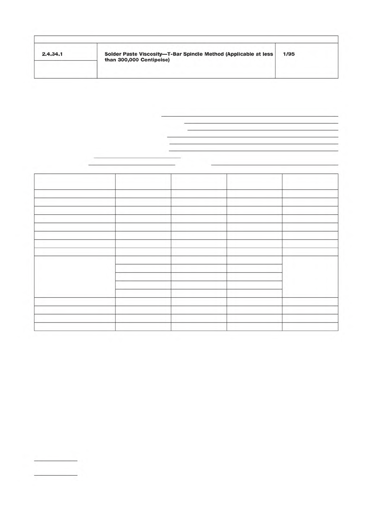
Table 1 Test Report on Solder Paste
Enter appropriate information in top portion of report and complete report by entering the test results or checkmarks in the appropriate spaces.
Inspection Purpose: QPL I.D. Number:
__ Qualification Manufacturer’s Identification:
__ Quality Conformance A Manufacturer’s Batch Number:
__ Quality Conformance B Date of Manufacture:
__ Shelf-Life Extension Original Use-By Date:
__ Performance Revised Use-By Date:
Date Inspection Completed: Overall Results: __ Pass __ Fail
Inspection Performed by:
Witnessed by:
Inspections
User’s Actual
Requirement Test Result P/F (*) Tested by & Date
Material
Visual
Metal Content
Viscosity
Solder Ball
Slump
Alloy
Flux
Powder Size
% In Top Screen
% In Next Screen
% In Bottom Screen
% In Receiver Bottom
Max. Powder Size
Powder Shape
Tack
Wetting
* P/F = PASS/FAIL; enter P if test results are within tolerance of actual requirement; otherwise, enter F
IPC-TM-650
Number
Subject Date
Revision
Page 2 of 2
2.4.34.1
Solder
Paste
Viscosity
―
T-Bar
Spindle
Method
(Applicable
at
less
than
300,000
Centipoise)
1/95