IPC-TM-650 EN 2022 试验方法--.pdf - 第706页
Ultrasonic T est Data Record Name of tester Date Company Address Phone Fax Make and model of equipment T ank size Dimensions ( cm cm x cm) Generator output power Frequency (KHz) No. of boards tested per trial Substrate E…
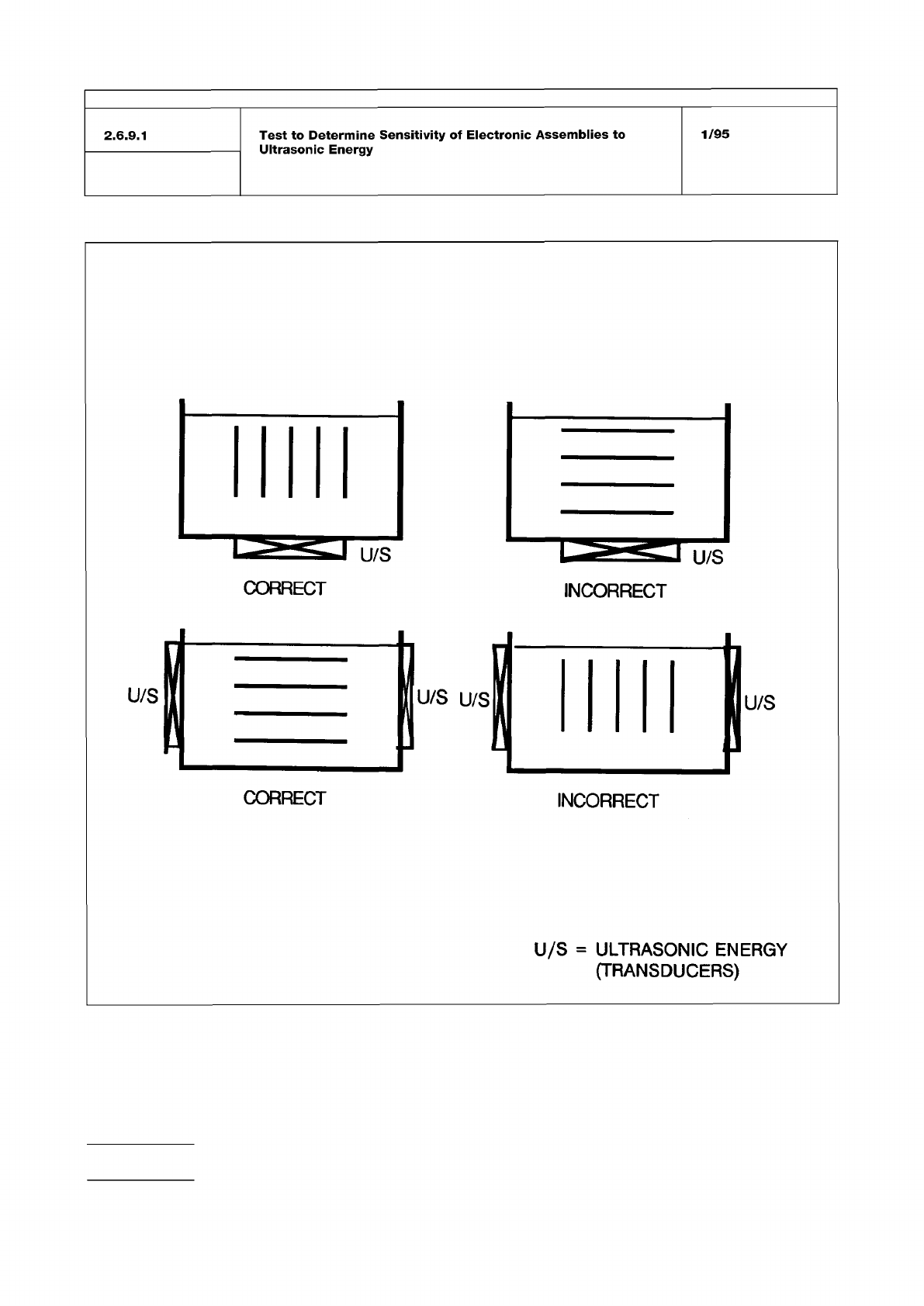
Figure 1
IPC-TM-650
Number
Subject Date
Revision
Page 4 of 5
2.6.9.1
Test
to
Determine
Sensitivity
of
Electronic
Assemblies
to
Ultrasonic
Energy
1/95
INCORRECT
CORRECT
INCORRECT
U/S
=
ULTRASONIC
ENERGY
(TRANSDUCERS)
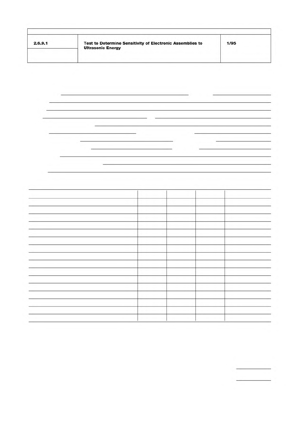
Ultrasonic Test Data Record
Name of tester Date
Company
Address
Phone Fax
Make and model of equipment
Tank size Dimensions (cm cm x cm)
Generator output power Frequency (KHz)
No. of boards tested per trial Substrate
Exposure time
Other stress testing (pre- or post-)
Describe
Component tested No. tested Passed Failed Comments
Type Mfgr Part #
Mail to: IPC Fax to: 847-509-9798
2215 Sanders Road
Northbrook, IL 60062-6135
Attn: Ultrasonic Cleaning Task Group
IPC-TM-650
Number
Subject Date
Revision
Page 5 of 5
2.6.9.1
Test
to
Determine
Sensitivity
of
Electronic
Assemblies
to
Ultrasonic
Energy
1/95
Ultrasound:
Frequency:
Generator:
Transducers:
Piezoelectric:
Magnetostrictive:
Cavitation:
Degas:
Power Density:
IPC-T-50
IPC-CH-65
J-STD-001
MIL-STD-2000 Rev. A
IEC-TC-91
The Institute for Interconnecting and Packaging Electronic Circuits
2215 Sanders Road • Northbrook, IL 60062-6135
Material in this Test Methods Manual was voluntarily established by Technical Committees of the IPC. This material is advisory only
and its use or adaptation is entirely voluntary. IPC disclaims all liability of any kind as to the use, application, or adaptation of this
material. Users are also wholly responsible for protecting themselves against all claims or liabilities for patent infringement.
Equipment referenced is for the convenience of the user and does not imply endorsement by the IPC.
Page 1 of 4
IPC-TM-650
TEST
METHODS
MANUAL
1
.0
Scope
The
purpose
of
this
test
method
is
to
provide
a
consistent
procedure
to
test
the
sensitivity
of
electronic
com¬
ponents
to
ultrasonic
energy.
There
has
been
reluctance
in
the
electronics
industry
to
use
ultrasonic
energy
for
printed
board
assembly
cleaning
because
of
the
possibility
of
damage
to
wire
bonds
in
active,
hermetically
sealed
components
or
other
damage
that
might
cause
latent
failures.
Recent
work
has
shown
that
electronic
components
have
a
low
potential
for
damage
from
ultrasonics
(References
1-7)
under
conditions
seen
in
most
cleaning
processes.
In
addi¬
tion,
MIL-STD-2000
Rev.
A
and
J-STD-001
now
allow
for
the
use
of
ultrasonic
cleaning,
as
does
the
proposal
for
I
EC
TC91
International
Standards
based
on
an
updated
revision
of
the
J-STD-001
.
1.1
Definitions
All
sound
in
frequencies
above
the
range
of
human
hearing.
For
the
purpose
of
ultrasonic
cleaning,
fre¬
quencies
between
1
8-800
KHz
are
in
commercial
use.
In
the
lower
frequency
ranges,
fluid
cavitation
is
the
primary
agitation
method.
In
the
higher
frequency
ranges,
microstreaming
(i.e.,
fluid
pumping)
is
believed
to
be
the
form
of
mechanical
agitation.
The
number
of
periodic
oscillations,
vibrations
of
waves
per
unit
of
time,
usually
expressed
in
cycles
per
second
(Hertz).
An
electronic
system
which
converts
the
50
or
60
Hz
power
line
electricity
into
an
ultrasonic
frequency
drive
sig¬
nal
which
powers
the
transducers
in
their
resonant
frequency
range.
Convert
electrical
energy
from
the
generator
into
mechanical
(vibratory)
energy,
producing
high
intensity
sound
waves
in
a
liquid
and
causing
cavitation
of
microstreaming.
Transducers
are
primarily
of
two
types,
piezoelectric
and
mag¬
netostrictive.
Piezoelectric
ceramics,
which
change
dimen¬
sions
in
the
presence
of
an
electric
field.
Thickness
varies
in
response
to
an
applied
voltage.
Conversion
efficiency
=
70-90%.
Made
of
nickel
or
its
alloys,
it
changes
length
when
placed
in
a
magnetic
field.
Conversion
efficiency
=
20-50%.
Number
2.6.9.2
Subject
Test
to
Determine
Sensitivity
of
Electronic
Components
to
Ultrasonic
Energy
Date
Revision
1/95
Originating
Task
Group
Ultrasonic
Cleaning
Task
Group
(5-31
e)
The
rapid
formation
and
oscillation
or
violent
col¬
lapse
of
microscopic
bubbles
or
cavities
in
a
liquid,
produced
by
introducing
high
frequency
(ultrasonic)
sound
waves
into
a
liquid.
The
agitation
from
countless
implosions
of
these
bubbles
create
a
highly
effective
scrubbing
of
both
exposed
and
hidden
surfaces
of
parts
immersed
in
the
cleaning
solu¬
tion.
The
act
of
removing
entrained
gas
from
cleaning
fluid.
Gas
bubbles
tend
to
absorb
ultrasonic
energy,
thereby
decreasing
the
amount
of
energy
available
for
cleaning.
Average
output
power
of
ultrasonic
generator
divided
by
total
volume
of
liquid
being
sonified.
2
.0
Applicable
Documents
2.1
Institute
for
Interconnecting
and
Packaging
Elec¬
tronic
Circuits
(I
PC)
Terms
and
Definitions
for
Interconnecting
and
Packaging
Electronic
Assemblies
Guidelines
for
Cleaning
of
Printed
Boards
and
Assemblies.
2.2
Joint
Industry
Standards
Requirements
for
Soldered
Electrical
and
Elec¬
tronic
Assemblies
2.3
Military
Standard
Requirements
for
Soldered
Electrical
and
Electronic
Assemblies
2.4
Other
Publications
Proposed
International
Standard
(based
on
J-STD-001)
International
Requirements
for
Soldered
Electrical
and
Electronic
Assemblies
using
Surface
Mount
and
Related
Assembly
Technologies.
3
.0
Test
Specimens
The
components
to
be
tested
should
be
the
exact
type
and
package
style
the
tester
intends
to
use
in
production.
A
statistically
valid
number
of
each
type
and
package
style
of
interest
should
be
tested.
4
.0
Apparatus