IPC-TM-650 EN 2022 试验方法--.pdf - 第342页
Not e: The Institute for Int erconnecting and Packaging E lectronic Circuits 2215 S anders Road • Northbrook, IL 60062-6135 Material in this T est M ethods Manual was voluntarily establis hed by T echni cal Committees of…
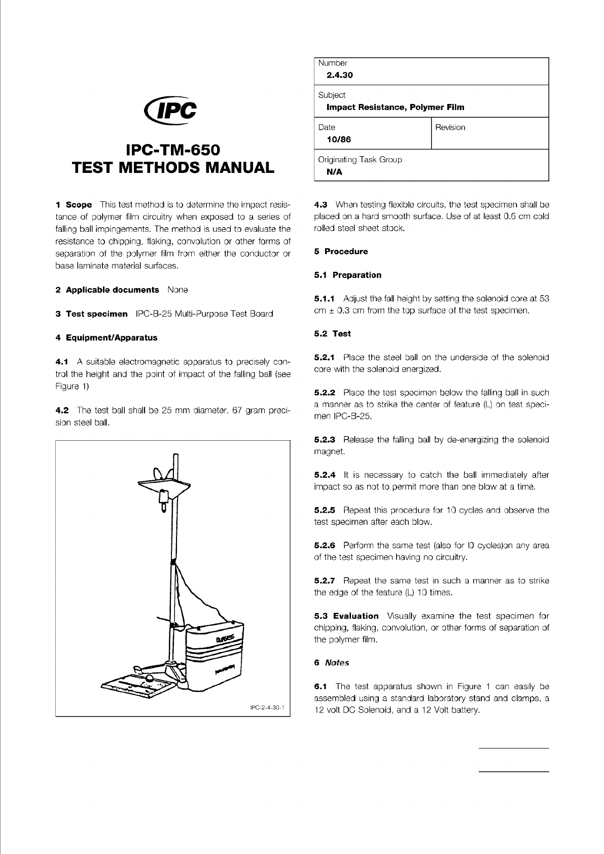
Figure 1 Falling Ball Impact Test Apparatus
The Institute for Interconnecting and Packaging Electronic Circuits
2215 Sanders Road • Northbrook, IL 60062-6135
Material in this Test Methods Manual was voluntarily established by Technical Committees of the IPC. This material is advisory only
and its use or adaptation is entirely voluntary. IPC disclaims all liability of any kind as to the use, application, or adaptation of this
material. Users are also wholly responsible for protecting themselves against all claims or liabilities for patent infringement.
Equipment referenced is for the convenience of the user and does not imply endorsement by the IPC.
Page 1 of 1
IPC-TM-650
TEST
METHODS
MANUAL
1
Scope
This
test
method
is
to
determine
the
impact
resis¬
tance
of
polymer
film
circuitry
when
exposed
to
a
series
of
falling
ball
impingements.
The
method
is
used
to
evaluate
the
resistance
to
chipping,
flaking,
convolution
or
other
forms
of
separation
of
the
polymer
film
from
either
the
conductor
or
base
laminate
material
surfaces.
2
Applicable
documents
None
3
Test
specimen
IPC-B-25
Multi-Purpose
Test
Board
4
Equipment/Apparatus
4.1
A
suitable
electromagnetic
apparatus
to
precisely
con¬
trol
the
height
and
the
point
of
impact
of
the
falling
ball
(see
Figure
1)
4.2
The
test
ball
shall
be
25
mm
diameter,
67
gram
preci¬
sion
steel
ball.
Number
2.4.30
Subject
Impact
Resistance,
Polymer
Film
Date
Revision
10/86
Originating
Task
Group
N/A
4.3
When
testing
flexible
circuits,
the
test
specimen
shall
be
placed
on
a
hard
smooth
surface.
Use
of
at
least
0.6
cm
cold
rolled
steel
sheet
stock.
5
Procedure
5.1
Preparation
5.1.1
Adjust
the
fall
height
by
setting
the
solenoid
core
at
53
cm
±
0.3
cm
from
the
top
surface
of
the
test
specimen.
5.2
Test
5.2.1
Place
the
steel
ball
on
the
underside
of
the
solenoid
core
with
the
solenoid
energized.
5.2.2
Place
the
test
specimen
below
the
falling
ball
in
such
a
manner
as
to
strike
the
center
of
feature
(L)
on
test
speci¬
men
IPC-B-25.
5.2.3
Release
the
falling
ball
by
de-energizing
the
solenoid
magnet.
5.2.4
It
is
necessary
to
catch
the
ball
immediately
after
impact
so
as
not
to
permit
more
than
one
blow
at
a
time.
5.2.5
Repeat
this
procedure
for
10
cycles
and
observe
the
test
specimen
after
each
blow.
5.2.6
Perform
the
same
test
(also
for
IO
cyclesjon
any
area
of
the
test
specimen
having
no
circuitry.
5.2.7
Repeat
the
same
test
in
such
a
manner
as
to
strike
the
edge
of
the
feature
(L)
10
times.
5.3
Evaluation
Visually
examine
the
test
specimen
for
chipping,
flaking,
convolution,
or
other
forms
of
separation
of
the
polymer
film.
6
Notes
6.1
The
test
apparatus
shown
in
Figure
1
can
easily
be
assembled
using
a
standard
laboratory
stand
and
clamps,
a
12
volt
DC
Solenoid,
and
a
12
Volt
battery.
Note:
The Institute for Interconnecting and Packaging Electronic Circuits
2215 Sanders Road • Northbrook, IL 60062-6135
Material in this Test Methods Manual was voluntarily established by Technical Committees of the IPC. This material is advisory only
and its use or adaptation is entirely voluntary. IPC disclaims all liability of any kind as to the use, application, or adaptation of this
material. Users are also wholly responsible for protecting themselves against all claims or liabilities for patent infringement.
Equipment referenced is for the convenience of the user and does not imply endorsement by the IPC.
Page 1 of 2
IPC-TM-650
TEST
METHODS
MANUAL
1
.0
Scope
The
test
specifies
a
standard
procedure
for
determining
the
viscosity
of
solder
paste
in
the
range
of
300,000
to
1
,600,000
centipoise.
2
.0
Applicable
Documents
None
3
.0
Test
Specimen
Paste
to
be
tested
shall
be
stabilized
at
25°
±
1
℃
for
a
minimum
of
24
hr.
prior
to
testing.
The
paste
volume
shall
be
sufficient
to
fill
a
test
container
having
a
minimum
diameter
of
5
cm
and
a
minimum
depth
of
5
cm.
4
.0
Equipment/Apparatus
The
equipment
used
shall
be
a
spindle
type
viscometer
(Brookfield
RVTD
or
equivalent)
with
a
reversible
helipath
stand
and
pen
recorder.
A
TF
spindle
shall
be
used
for
tests
and
operated
at
5
rpm.
Other
equipment
may
be
used
provided
the
results
can
be
empirically
corre¬
lated
as
mutually
agreed
upon
with
the
following
test.
Addi¬
tional
shear
rates
may
be
specified
by
the
user
or
supplier
provided
one
data
point
is
based
as
specified
below.
5
.0
Procedure
5.1
Preparation
5.1.1
Open
the
supply
container(s);
remove
any
internal
cov¬
ers),
scrape
off
paste
adhering
to
the
lid(s),
internal
covers,
and
the
container
walls;
and
add
this
material
to
the
paste
in
the
supply
container(s).
5.1.2
Using
a
spatula,
stir
the
paste
gently
for
1
to
2
minutes
to
homogenize
it;
taking
care
to
avoid
the
introduction
of
air.
5.1.3
If
necessary,
gently
transfer
the
paste
to
the
test
con¬
tainer
having
the
specified
volume;
without
introducing
air.
If
the
supply
container
meets
the
volume
and
size
requirements
a
separate
test
container
is
not
needed.
5.1.4
The
test
container
shall
be
placed
in
a
constant
tem¬
perature
environment
at
25
±
0.25℃.
The
solder
paste
shall
remain
stationary
for
a
minimum
of
two
hours
to
reach
tem¬
perature
and
rheological
equilibrium.
For
freshly
manufactured
Number
2.4.34
Subject
Solder
Paste
Viscosity
—
T-Bar
Spin
Spindle
Method
(Applicable
for
300,000
to
1,600,000
Centipoise)
Date
Revision
1/95
Originating
Task
Group
Solder
Paste
Task
Group
(5-24b)
products,
products
which
require
significant
adjustment
with
thinner
(greater
than
1/2%
by
weight),
or
products
having
rheological
characteristics
requiring
longer
time
to
stabilize,
the
stabilization
time
shall
be
increased
to
four
hours
or
as
mutually
agreed
upon
by
user
and
supplier.
5.1.5
Set
the
bottom
stop
for
heli
path
travel
to
position
the
T
spindle
at
2.8
cm
below
the
surface
of
the
solder
paste
in
the
test
container.
The
bottom
stop
of
the
spindle
shall
be
a
minimum
of
1
cm
above
the
bottom
of
the
container.
Set
the
upper
stop
to
position
the
spindle
at
0.3
cm
below
the
surface
of
the
solder
paste.
5.2
Test
5.2.1
Immerse
the
spindle
in
the
solder
paste
and
record
data
for
10
minutes
(5
cycles).
The
temperature
of
the
solder
paste
during
the
test
shall
be
maintained
at
25
土
0.25℃.
5.3
Evaluation
Viscosity
is
to
be
expressed
at
the
value
calculated
from
the
average
of
the
peak
and
valley
of
the
last
two
cycles.
If
the
average
for
the
first
two
cycles
is
more
than
10%
higher
than
the
last
two
cycles,
the
test
is
invalid
and
additional
equilibrium
time
is
required.
Record
data
and
enter
in
Table
1
,
“Test
Report
on
Solder
Paste.”
6
.0
Notes
6.1
Test
Equipment
Sources
The
equipment
sources
described
below
represent
those
currently
known
to
the
industry.
Users
of
this
test
method
are
urged
to
submit
addi¬
tional
source
names
as
they
become
available,
so
that
this
list
can
be
kept
as
current
as
possible.
6.1.1
Spindle
Type
Viscometer
Equipment
Brookfield
Engineering
Laboratories,
Inc.
240
Cushing
Street
Stoughton,
MA
02072
(617)
344-4310
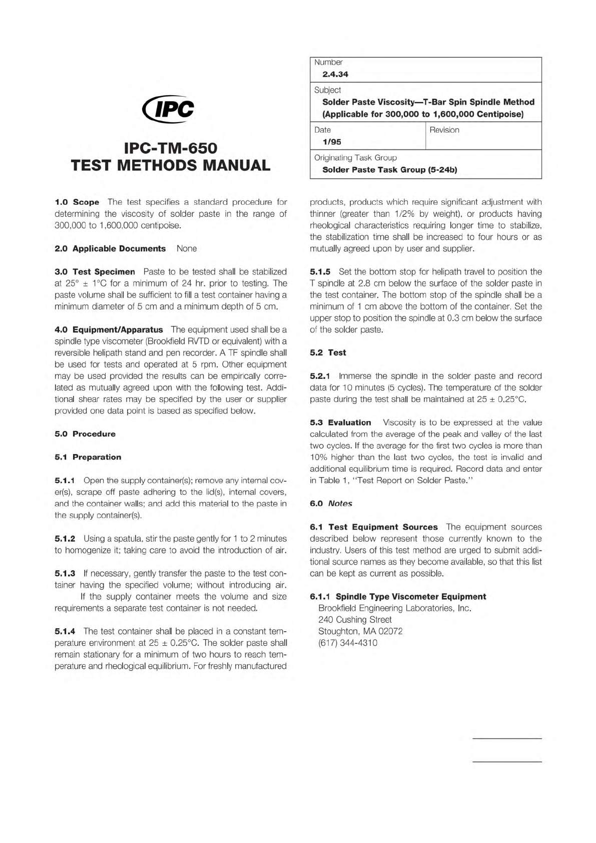
Table 1 Test Report on Solder Paste
Enter appropriate information in top portion of report and complete report by entering the test results or checkmarks in the appropriate spaces.
Inspection Purpose: QPL I.D. Number:
__ Qualification Manufacturer’s Identification:
__ Quality Conformance A Manufacturer’s Batch Number:
__ Quality Conformance B Date of Manufacture:
__ Shelf-Life Extension Original Use-By Date:
__ Performance Revised Use-By Date:
Date Inspection Completed: Overall Results: __ Pass __ Fail
Inspection Performed by:
Witnessed by:
Inspections
User’s Actual
Requirement Test Result P/F (*) Tested by & Date
Material
Visual
Metal Content
Viscosity
Solder Ball
Slump
Alloy
Flux
Powder Size
% In Top Screen
% In Next Screen
% In Bottom Screen
% In Receiver Bottom
Max. Powder Size
Powder Shape
Tack
Wetting
* P/F = PASS/FAIL; enter P if test results are within tolerance of actual requirement; otherwise, enter F
IPC-TM-650
Number
Subject Date
Revision
Page 2 of 2
2.4.34
Solder
Paste
Viscosity
―
T-Bar
Spin
Spindle
Method
(Applicable
for
300,000
to
1,600,000
Centipoise)
1/95