IPC-TM-650 EN 2022 试验方法--.pdf - 第366页
AS T M- E- 22 8 ASTM-D-696 ASTM- E- 831 ASTM -E-77 ASTM-E-220 ASTM-E-644 The Institute for Int erconnecting and Packaging E lectronic Circuits 2215 S anders Road • Northbrook, IL 60062-6135 Material in this T est M ethod…
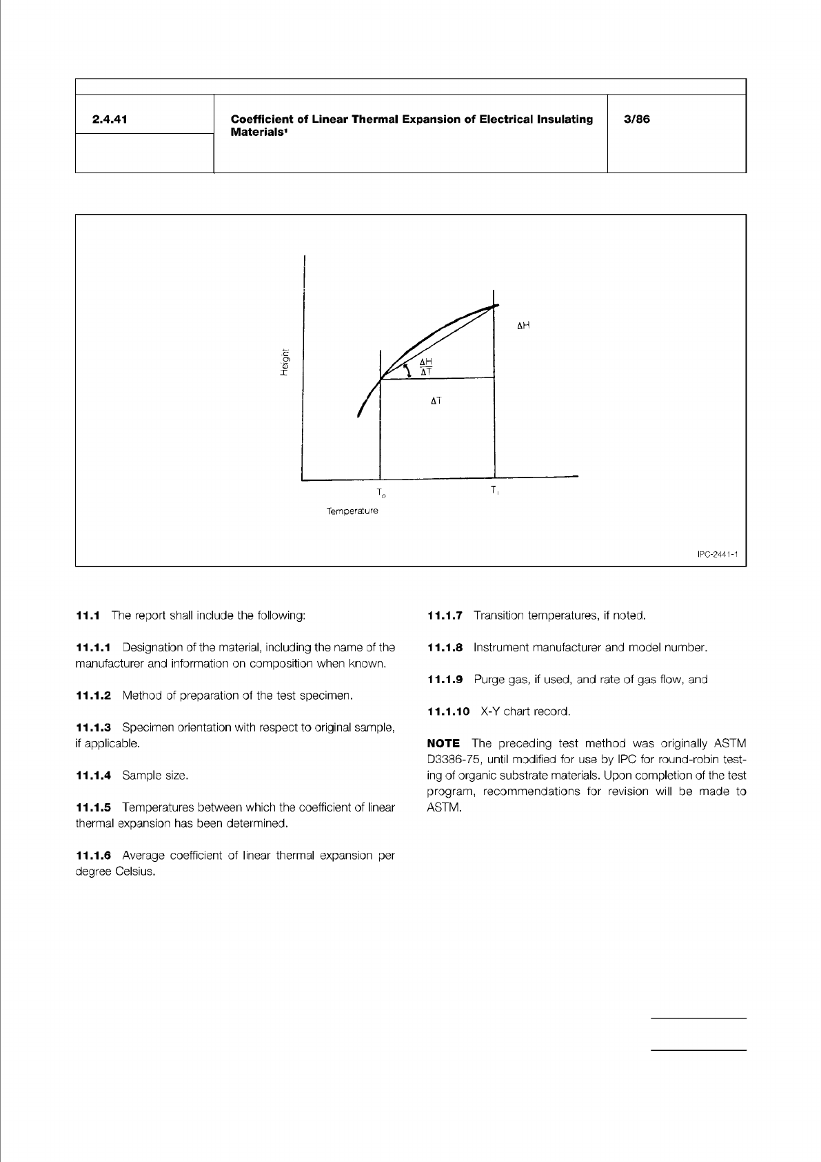
Figure 1 Specimen height versus temperature
IPC-TM-650
Number
Subject Date
Revision
Page 3 of 3
2.4.41
Coefficient
of
Linear
Thermal
Expansion
of
Electrical
Insulating
Materials1
3/86
Temperature
IPC-2441-1
11.1
The
report
shall
include
the
following:
11.1.7
Transition
temperatures,
if
noted.
11.1.1
Designation
of
the
material,
including
the
name
of
the
manufacturer
and
information
on
composition
when
known.
11.1.2
Method
of
preparation
of
the
test
specimen.
11.1.3
Specimen
orientation
with
respect
to
original
sample,
if
applicable.
11.1.4
Sample
size.
11.1.5
Temperatures
between
which
the
coefficient
of
linear
thermal
expansion
has
been
determined.
11.1.8
Instrument
manufacturer
and
model
number.
11.1.9
Purge
gas,
if
used,
and
rate
of
gas
flow,
and
11.1.10
X-Y
chart
record.
NOTE
The
preceding
test
method
was
originally
ASTM
D3386-75,
until
modified
for
use
by
IPG
for
round-robin
test¬
ing
of
organic
substrate
materials.
Upon
completion
of
the
test
program,
recommendations
for
revision
will
be
made
to
ASTM.
11.1.6
Average
coefficient
of
linear
thermal
expansion
per
degree
Celsius.
ASTM-E-228
ASTM-D-696
ASTM-E-831
ASTM-E-77
ASTM-E-220
ASTM-E-644
The Institute for Interconnecting and Packaging Electronic Circuits
2215 Sanders Road • Northbrook, IL 60062-6135
Material in this Test Methods Manual was voluntarily established by Technical Committees of the IPC. This material is advisory only
and its use or adaptation is entirely voluntary. IPC disclaims all liability of any kind as to the use, application, or adaptation of this
material. Users are also wholly responsible for protecting themselves against all claims or liabilities for patent infringement.
Equipment referenced is for the convenience of the user and does not imply endorsement by the IPC.
Page 1 of 3
IPC-TM-650
TEST
METHODS
MANUAL
Number
2.4.41.1
Subject
Coefficient
of
Thermal
Expansion
by
the
Vitreous
Silica
(Quartz)
Dilatometer
Method
Date
Revision
8/97
A
Originating
Task
Group
N/A
1
.0
Scope
1.1
To
describe
the
vitreous
silica
dilatometer
method
for
determining
the
linear
thermal
expansion
of
laminated
materi¬
als
within
the
temperature
range
of
-55℃
to
1
00℃.
Inorganic
substrates
(non-laminated)
shall
be
tested
within
a
range
of
-55°
to
150℃.
2
.0
Applicable
Documents
Standard
Test
Method
for
Linear
Thermal
Expansion
of
Solid
Materials
with
a
Vitreous
Silica
Dilatometer
Test
for
Coefficient
of
Linear
Thermal
Expan¬
sion
of
Plastics
Test
for
Linear
Thermal
Expansion
of
Solid
Materials
by
Thermodilatometry
Verification
and
Calibration
of
Liquid-in-Glass
Thermometers
Calibration
of
Thermocouples
by
Comparison
Techniques
Testing
Industrial
Resistance
Thermometers
3
.0
Test
Specimen
3.1
Laminated
materials
which
may
or
may
not
contain
metal
layers.
3.2
Nominal
test
specimen
dimensions
shall
be
1/4
inch
wide
x
2
inch
-4
inch
long
x
1/8
inch
minimum
thickness.
End
surfaces
shall
be
ground
parallel.
Any
deviation
from
nominal
should
recognize
thermal
gradients
of
the
temperature
cham¬
ber,
thermal
lag
of
specimen
and
any
bending
of
specimen.
Thicknesses
under
1/8
inch
shall
be
supported
by
adequate
clamping
devices
unless
it
is
certain
that
the
specimen
will
remain
straight
during
testing.
4
.0
Apparatus
4.1
Vitreous
silica
dilatometer
of
either
the
tube
or
push
rod
type
to
determine
the
change
in
length
of
a
solid
material
as
a
function
of
temperature.
The
temperature
is
controlled
at
a
constant
heating
or
cooling
rate.
The
linear
thermal
expansion
and
the
coefficients
of
linear
thermal
expansion
(GTE)
are
cal¬
culated
from
the
recorded
data.
This
device
measures
the
difference
in
thermal
expansion
between
a
test
specimen
and
the
vitreous
silica
parts
of
the
dilatometer
(Figure
1).
4.2
Specimen
holder
(tube)
and
probe
shall
be
made
of
vit¬
reous
silica.
The
probe
contact
shall
be
flat
or
be
rounded
to
approximately
a
1
0
mm
radius.
4.3
Chamber
for
uniformly
heating
and
cooling
the
speci¬
men.
The
specimen
temperature
change
rate
shall
be
con¬
trolled.
The
temperature
gradient
in
the
specimen
shall
not
exceed
0.5℃/cm.
4.4
Transducer,
for
measuring
the
difference
in
length
between
the
specimen
and
the
specimen
holder
with
an
accuracy
of
at
least
士
0.5|jm.
The
transducer
shall
be
pro¬
tected
or
mounted
so
that
temperature
changes
will
not
affect
the
readings
by
more
than
1
.Opm.
4.5
Micrometer,
for
measuring
the
reference
length,
Lo,
of
the
specimen
with
an
accuracy
of
at
least
±
25|jm.
4.6
Thermocouple,
types
E,
K,
or
T,
for
measurement
of
the
specimen
temperature.
(Type
E
is
NiCr
versus
constantan,
type
K
is
NiCr
versus
NiAI
and
Type
T
is
Cu
versus
constan¬
tan.)
4.7
Recorder
or
data
logger
for
collecting
temperatures
and
lengths.
5
.0
Procedure
5.1
Sample
Preparation
Rough
cut
with
a
band
saw
or
metallurgical
cut-off
wheel
and
finish
machining
by
grinding.
Care
must
be
exercised
to
remove
roughness
from
specimen
ends.
The
ends
shall
be
parallel
to
土
.001
inch/inch.
5.2
Sample
condition
(only
for
laminated,
organic
speci¬
mens).
5.2.1
The
specimen
shall
be
immersed
in
isopropyl
alcohol
and
agitated
for
twenty
seconds.
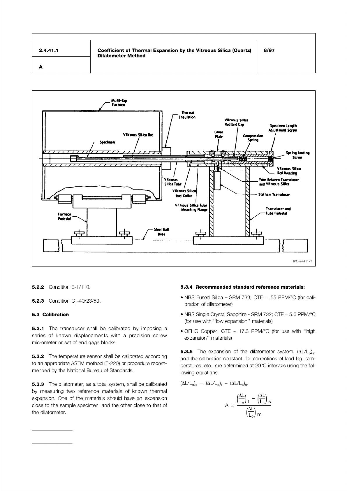
Figure 1 Cutaway view of vitreous silica tube dilatometer
IPC-TM-650
Number
Subject Date
Revision
Page 2 of 3
5.2.2
Condition
E-1/1
10.
5.3.4
Recommended
standard
reference
materials:
5.2.3
Condition
-40/23/50.
5.3
Calibration
5.3.2
The
temperature
sensor
shall
be
calibrated
according
to
an
appropriate
ASTM
method
(E-220)
or
procedure
recom¬
mended
by
the
National
Bureau
of
Standards.
•
OFHC
Copper;
GTE
1
7.3
PPM/℃
(for
use
with
“high
expansion"
materials)
5.3.3
The
dilatometer,
as
a
total
system,
shall
be
calibrated
by
measuring
two
reference
materials
of
known
thermal
expansion.
One
of
the
materials
should
have
an
expansion
close
to
the
sample
specimen,
and
the
other
close
to
that
of
the
dilatometer.
5.3.1
The
transducer
shall
be
calibrated
by
imposing
a
series
of
known
displacements
with
a
precision
screw
micrometer
or
set
of
end
gage
blocks.
•
NBS
Fused
Silica
-
SRM
739;
CTE
.55
PPM/℃
(for
cali¬
bration
of
dilatometer)
5.3.5
The
expansion
of
the
dilatometer
system,
(AL/LO)S,
and
the
calibration
constant,
for
corrections
of
lead
lag,
tem¬
peratures,
etc.,
are
determined
at
20℃
intervals
using
the
fol¬
lowing
equations:
(A^LO)S
=
(AULJ
-
(AULJm
•
NBS
Single
Crystal
Sapphire
-
SRM
732;
CTE
~
5.5
PPM/℃
(for
use
with
l1ow
expansion"
materials)
尚
「代)
s
A
=
2.4.41.1
A
Coefficient
of
Thermal
Expansion
by
the
Vitreous
Silica
(Quartz)
Dilatometer
Method
8/97
给
m