IPC-TM-650 EN 2022 试验方法--.pdf - 第687页
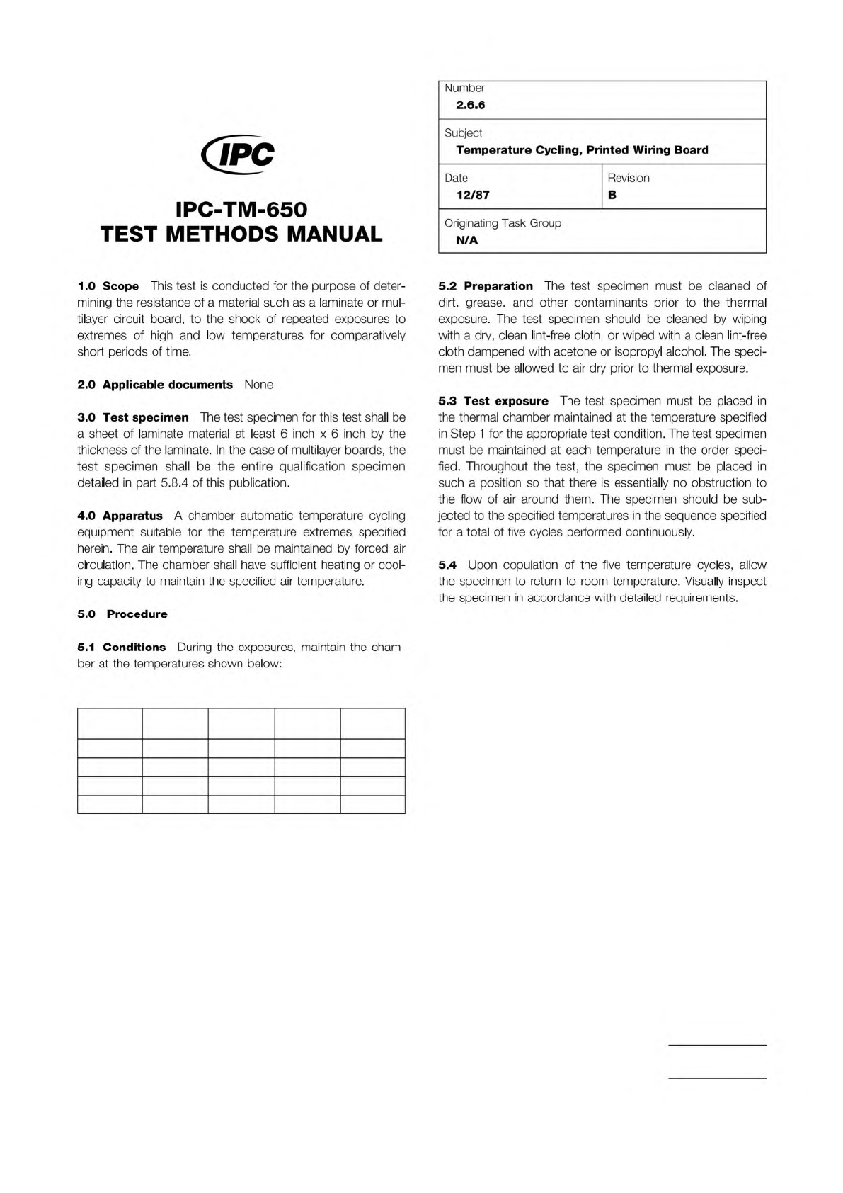
Class A Class B Step T emp. (°C) Time (Min.) T em p. (°C) Time (Min.) 1 125+3/–0 3 0 85 +3/–0 30 2 25+10/–5 10–15 25+10/–5 10–15 3 –65+0/–5 3 0 –55 +0/–5 30 4 25+10/–5 10–15 25+10/–5 10–15 The Institute for Int erconnect…
Material in this Test Methods Manual was voluntarily established by Technical Committees of IPC. This material is advisory only
and its use or adaptation is entirely voluntary. IPC disclaims all liability of any kind as to the use, application, or adaptation of this
material. Users are also wholly responsible for protecting themselves against all claims or liabilities for patent infringement.
Equipment referenced is for the convenience of the user and does not imply endorsement by IPC.
Page 1 of 1
r
ASSOCIATION
CONNECTING
/
ELECTRONICS
INDUSTRIES
®
221
5
Sanders
Road
Northbrook,
IL
60062-6135
IPC-TM-650
TEST
METHODS
MANUAL
1
Scope
This
method
is
to
determine
the
electrical
perfor¬
mance
of
multilayer
printed
wiring
boards
by
following
the
shock
with
an
electrical
continuity
test
as
specified.
2
Applicable
Documents
None
3
Test
Specimen
Complete
multilayer
printed
wiring
board
or
qualification
test
board
IPC-A-47.
4
Apparatus
4.1
A
standard
AVCO
150
pneumatic
drop
shock
tester,
or
equivalent,
capable
of
attaining
at
least
1
50
Gs.
4.2
High-speed
motion
picture
and
oscilloscope
photogra¬
phy
is
not
normally
necessary
and
is
not
recommended
for
the
average
“go
no-go"
testing
program.
Number
2.6.5
Subject
Physical
Shock,
Multilayer
Printed
Wiring
Originating
Task
Group
Rigid
Printed
Board
Performance
Task
Group
(D-33a)
Date
Revision
05/04
D
5
Procedure
5.1
Preparation
Fixture
the
test
pattern
boards
so
they
are
restrained
on
all
four
edges.
Fabricate
the
fixtures
so
that
it
can
be
oriented
to
test
the
boards
on
three
principle
planes.
5.2
Test
Subject
each
specimen
to
three
shock
pulses
of
100
Gs
with
a
duration
of
6.5
milliseconds
in
each
of
the
three
principle
planes
—
a
total
of
nine
blows.
5.3
Evaluation
Subject
each
specimen
to
a
continuity
test
as
specified.
6
Notes
None
Class A Class B
Step
Temp.
(°C)
Time
(Min.)
Temp.
(°C)
Time
(Min.)
1 125+3/–0 30 85+3/–0 30
2 25+10/–5 10–15 25+10/–5 10–15
3 –65+0/–5 30 –55+0/–5 30
4 25+10/–5 10–15 25+10/–5 10–15
The Institute for Interconnecting and Packaging Electronic Circuits
2215 Sanders Road • Northbrook, IL 60062-6135
Material in this Test Methods Manual was voluntarily established by Technical Committees of the IPC. This material is advisory only
and its use or adaptation is entirely voluntary. IPC disclaims all liability of any kind as to the use, application, or adaptation of this
material. Users are also wholly responsible for protecting themselves against all claims or liabilities for patent infringement.
Equipment referenced is for the convenience of the user and does not imply endorsement by the IPC.
Page 1 of 1
IPC-TM-650
TEST
METHODS
MANUAL
1
.0
Scope
This
test
is
conducted
for
the
purpose
of
deter¬
mining
the
resistance
of
a
material
such
as
a
laminate
or
mul¬
tilayer
circuit
board,
to
the
shock
of
repeated
exposures
to
extremes
of
high
and
low
temperatures
for
comparatively
short
periods
of
time.
2
.0
Applicable
documents
None
3
.0
Test
specimen
The
test
specimen
for
this
test
shall
be
a
sheet
of
laminate
material
at
least
6
inch
x
6
inch
by
the
thickness
of
the
laminate.
In
the
case
of
multilayer
boards,
the
test
specimen
shall
be
the
entire
qualification
specimen
detailed
in
part
5.8.4
of
this
publication.
4
.0
Apparatus
A
chamber
automatic
temperature
cycling
equipment
suitable
for
the
temperature
extremes
specified
herein.
The
air
temperature
shall
be
maintained
by
forced
air
circulation.
The
chamber
shall
have
sufficient
heating
or
cool¬
ing
capacity
to
maintain
the
specified
air
temperature.
5
.0
Procedure
Number
2.6.6
Subject
Temperature
Cycling,
Printed
Wiring
Board
Date
Revision
12/87
B
Originating
Task
Group
N/A
5.2
Preparation
The
test
specimen
must
be
cleaned
of
dirt,
grease,
and
other
contaminants
prior
to
the
thermal
exposure.
The
test
specimen
should
be
cleaned
by
wiping
with
a
dry,
clean
lint-free
cloth,
or
wiped
with
a
clean
lint-free
cloth
dampened
with
acetone
or
isopropyl
alcohol.
The
speci¬
men
must
be
allowed
to
air
dry
prior
to
thermal
exposure.
5.3
Test
exposure
The
test
specimen
must
be
placed
in
the
thermal
chamber
maintained
at
the
temperature
specified
in
Step
1
for
the
appropriate
test
condition.
The
test
specimen
must
be
maintained
at
each
temperature
in
the
order
speci¬
fied.
Throughout
the
test,
the
specimen
must
be
placed
in
such
a
position
so
that
there
is
essentially
no
obstruction
to
the
flow
of
air
around
them.
The
specimen
should
be
sub¬
jected
to
the
specified
temperatures
in
the
sequence
specified
for
a
total
of
five
cycles
performed
continuously.
5.4
Upon
copulation
of
the
five
temperature
cycles,
allow
the
specimen
to
return
to
room
temperature.
Visually
inspect
the
specimen
in
accordance
with
detailed
requirements.
5.1
Conditions
During
the
exposures,
maintain
the
cham¬
ber
at
the
temperatures
shown
below:
IPC-D-275
NOTE:
The Institute for Interconnecting and Packaging Electronic Circuits
2215 Sanders Road • Northbrook, IL 60062-6135
Material in this Test Methods Manual was voluntarily established by Technical Committees of the IPC. This material is advisory only
and its use or adaptation is entirely voluntary. IPC disclaims all liability of any kind as to the use, application, or adaptation of this
material. Users are also wholly responsible for protecting themselves against all claims or liabilities for patent infringement.
Equipment referenced is for the convenience of the user and does not imply endorsement by the IPC.
Page 1 of 2
IPC-TM-650
TEST
METHODS
MANUAL
1
.0
Scope
The
purpose
of
this
method
is
to
determine
the
physical
endurance
of
printed
boards
to
sudden
exposure
to
extreme
changes
in
temperature
and
the
effect
of
alternate
exposures
to
these
extremes.
The
exposure
of
the
printed
board
specimens
to
the
high
and
low
temperature
extremes
is
designed
to
cause
physical
damage,
deterioration,
or
signifi¬
cant
changes
in
resistance.
2
.0
Applicable
Documents
Design
Standard
for
Rigid
Printed
Boards
and
Rigid
Printed
Board
Assemblies.
3
.0
Test
Specimen
Test
coupon
“D”
from
IPC-D-275
or
other
suitable
test
coupon
(see
6.1a).
4
.0
Apparatus
4.1
An
automatically
controlled
dual
temperature
environ¬
mental
test
chamber
or
other
dual
chamber
apparatus
capable
of
maintaining
-65,-55,-40
or
0
℃
+
0
-5℃
[-85,
-67, -40,
+32°F
+
0
-9°F]
in
the
low
temperature
chamber
and
70,
85,
105,
125,
150
or
170
+5
-0℃
[158,
185,
221,
257,
302
or
338°
F
+9
-0°F]
in
the
high
temperature
chamber.
The
temperature
extremes
(high
and
low)
that
are
required
is
dependent
on
the
base
material
of
the
specimen
that
is
to
be
tested
(see
6.1b
).
The
recovery
capacity
of
the
test
chambers
shall
be
such
that
the
internal
chamber
air
tem¬
perature
shall
reach
the
specified
temperature
within
2
min¬
utes
after
the
specimen(s)
have
been
transferred
to
the
test
chamber.
4.2
An
electrical
resistance
meter
capable
of
accuracies
of
0.5
milliohm
or
better
with
Kelvin
(4
terminal)
type
leads.
A
Kelvin
type
double
bridge
or
potentiometer
of
the
specified
accuracy
may
also
be
used
(see
6.2).
5.1
Preparation
Wire
up
test
specimen
with
Kelvin
-type
leads
at
the
points
where
measurements
will
be
made.
Number
2.6.7
Subject
Thermal
Shock
&
Continuity,
Printed
Board
Date
Revision
8/97
A
Originating
Task
Group
Rigid
Board
T.M.
Task
Group,
7-1
1d
specimen
in
the
approximate
center
of
the
high
temperature
chamber.
First
specimens
shall
be
placed
approximately
13
mm
[0.5
in]
apart
and
aligned
in
a
manner
to
permit
maximum
heat
transfer
to
the
test
specimen(s).
5.2
Test
5.2.1
Thermal
Shock
Cycle
5.2.1.
1
The
specimens
shall
be
subjected
to
100
tempera¬
ture
cycles
in
accordance
with
the
applicable
test
condition
of
Table
1.
5.2.1.
2
Transfer
time
between
chambers
shall
be
less
than
2
minutes.
The
thermal
capacity
of
the
test
chamber
used
shall
be
such
that
the
ambient
temperature
shall
reach
the
specified
temperature
within
2
minutes
after
the
specimen
has
been
transferred
to
the
appropriate
chamber.
5.2.1.
3
Interconnection
resistance
measurements
shall
be
taken
before
the
test,
during
the
first
cycle
at
high
tempera¬
ture,
and
during
the
last
cycle
at
high
temperature.
In-cham-
ber
resistance
measurements
should
be
taken
during
the
last
few
minutes
of
chamber
exposure.
Care
should
also
be
taken
to
measure
samples
after
approximately
the
same
duration
at
chamber
temperature.
5.3
Evaluation
The
maximum
change
in
resistance
between
the
first
and
100th
cycle
shall
be
evaluated
for
acceptability
to
the
requirements
of
the
applicable
specifica¬
tion.
6.0
Notes
6.1
The
following
details
are
to
be
specified
in
the
applicable
performance
specification:
a.
Test
specimen,
if
other
than
specified
in
3.0.
b.
Test
condition,
if
other
than
specified
in
4.1
.
c.
Maximum
change
in
resistance.
5.1.1
Operate
chamber
(or
chambers)
and
allow
to
stabilize
at
the
high
and
low
temperature
required.
Clamp
or
suspend