IPC-TM-650 EN 2022 试验方法--.pdf - 第160页
Figure 1 IPC-TM-650 Number Subject Date Revision Page 3 of 3 2.3.17.2 Resin Flow of “No Flow" Prepreg 8/97 B IPC-23172-fig1
IPC-TM-650
Number
Subject Date
Revision
Page 2 of 3
8/97
2.3.17.2
Resin
Flow
of
uNo
Flow”
Prepreg
B
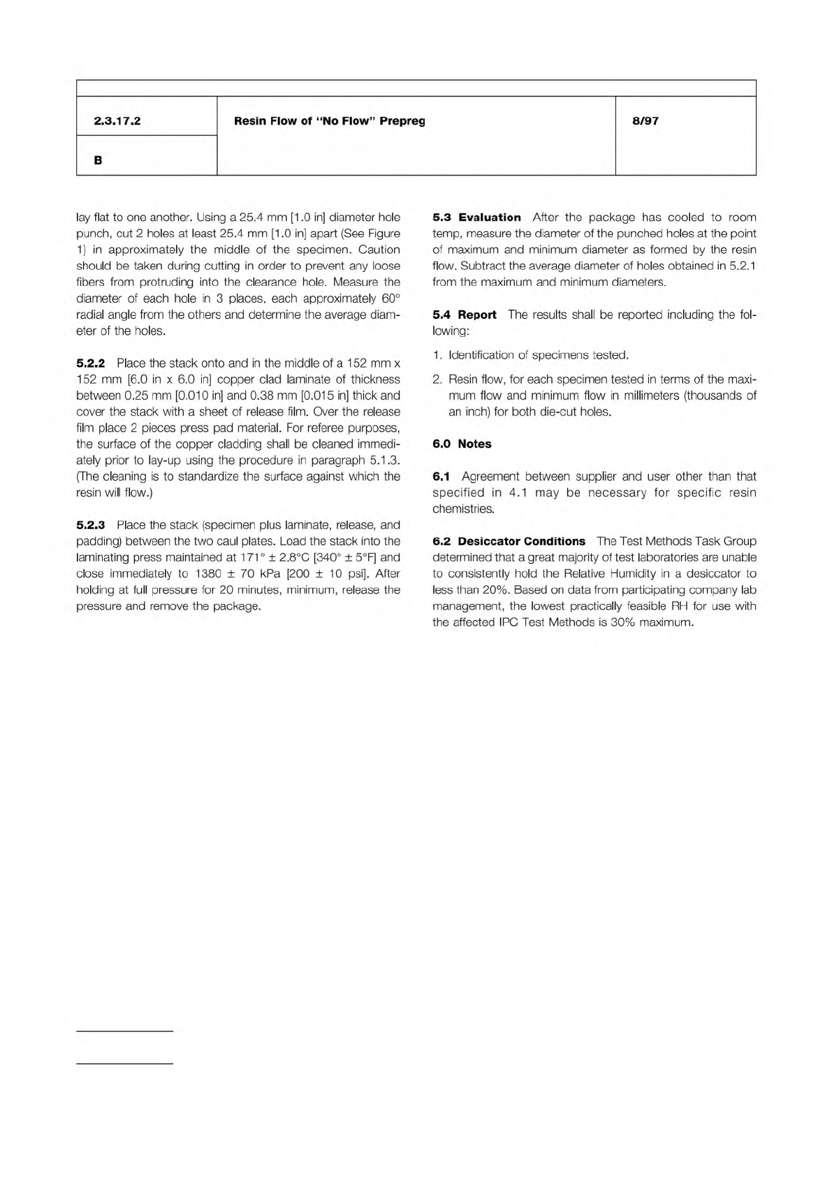
lay
flat
to
one
another.
Using
a
25.4
mm
[1.0
in]
diameter
hole
punch,
cut
2
holes
at
least
25.4
mm
[1.0
in]
apart
(See
Figure
1)
in
approximately
the
middle
of
the
specimen.
Caution
should
be
taken
during
cutting
in
order
to
prevent
any
loose
fibers
from
protruding
into
the
clearance
hole.
Measure
the
diameter
of
each
hole
in
3
places,
each
approximately
60°
radial
angle
from
the
others
and
determine
the
average
diam¬
eter
of
the
holes.
5.2.2
Place
the
stack
onto
and
in
the
middle
of
a
1
52
mm
x
152
mm
[6.0
in
x
6.0
in]
copper
clad
laminate
of
thickness
between
0.25
mm
[0.010
in]
and
0.38
mm
[0.015
in]
thick
and
cover
the
stack
with
a
sheet
of
release
film.
Over
the
release
film
place
2
pieces
press
pad
material.
For
referee
purposes,
the
surface
of
the
copper
cladding
shall
be
cleaned
immedi¬
ately
prior
to
lay-up
using
the
procedure
in
paragraph
5.1
.3.
(The
cleaning
is
to
standardize
the
surface
against
which
the
resin
will
flow.)
5.2.3
Place
the
stack
(specimen
plus
laminate,
release,
and
padding)
between
the
two
caul
plates.
Load
the
stack
into
the
laminating
press
maintained
at
1
7
1
°
±
2.8℃
[340°
±
5°F]
and
close
immediately
to
1380
±
70
kPa
[200
±
10
psi].
After
holding
at
full
pressure
for
20
minutes,
minimum,
release
the
pressure
and
remove
the
package.
5.3
Evaluation
After
the
package
has
cooled
to
room
temp,
measure
the
diameter
of
the
punched
holes
at
the
point
of
maximum
and
minimum
diameter
as
formed
by
the
resin
flow.
Subtract
the
average
diameter
of
holes
obtained
in
5.2.1
from
the
maximum
and
minimum
diameters.
5.4
Report
The
results
shall
be
reported
including
the
fol¬
lowing:
1.
Identification
of
specimens
tested.
2.
Resin
flow,
for
each
specimen
tested
in
terms
of
the
maxi¬
mum
flow
and
minimum
flow
in
millimeters
(thousands
of
an
inch)
for
both
die-cut
holes.
6.0
Notes
6.1
Agreement
between
supplier
and
user
other
than
that
specified
in
4.1
may
be
necessary
for
specific
resin
chemistries.
6.2
Desiccator
Conditions
The
Test
Methods
Task
Group
determined
that
a
great
majority
of
test
laboratories
are
unable
to
consistently
hold
the
Relative
Humidity
in
a
desiccator
to
less
than
20%.
Based
on
data
from
participating
company
lab
management,
the
lowest
practically
feasible
RH
for
use
with
the
affected
IPC
Test
Methods
is
30%
maximum.
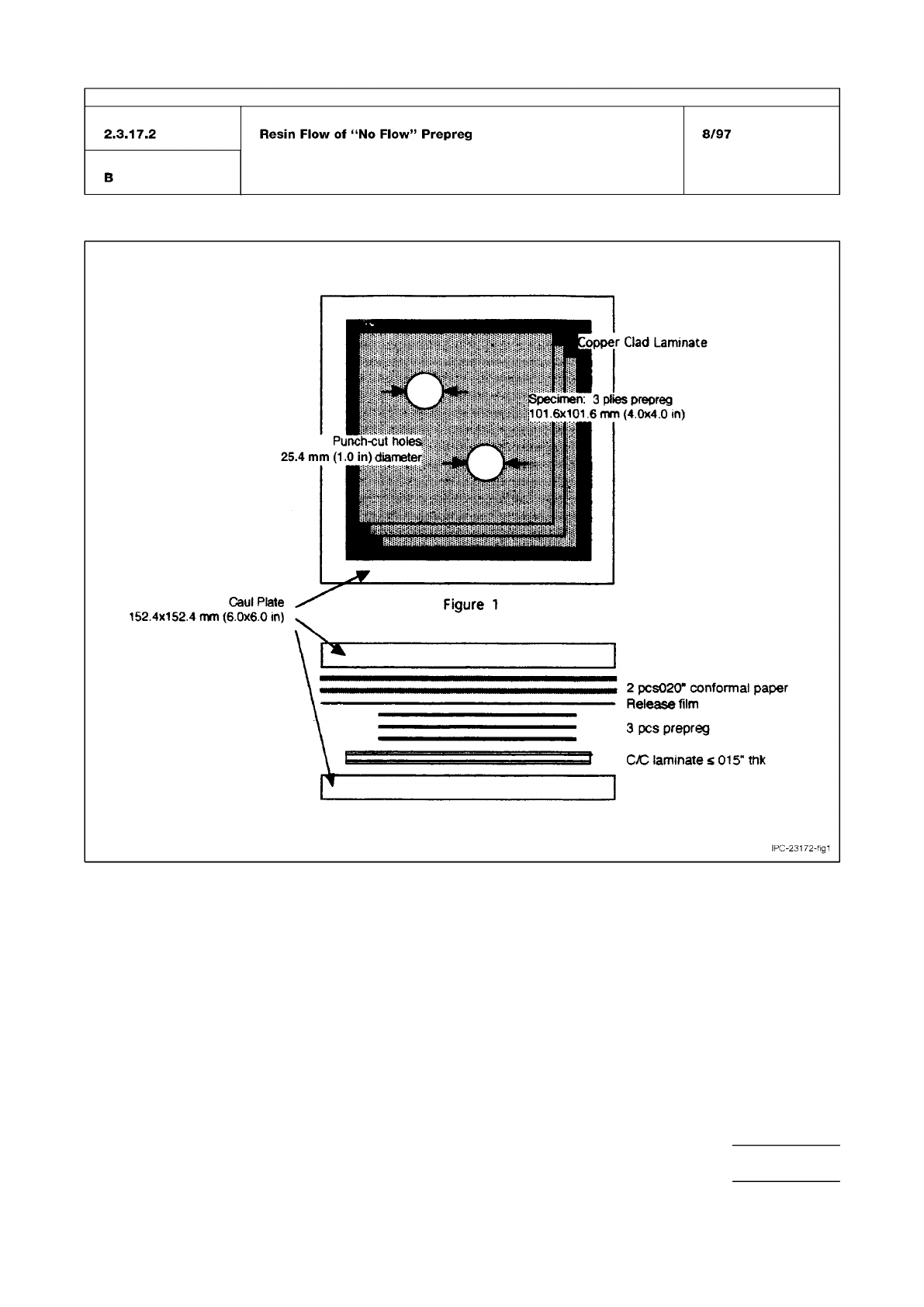
Figure 1
IPC-TM-650
Number
Subject Date
Revision
Page 3 of 3
2.3.17.2
Resin
Flow
of
“No
Flow"
Prepreg
8/97
B
IPC-23172-fig1
The Institute for Interconnecting and Packaging Electronic Circuits
2215 Sanders Road • Northbrook, IL 60062-6135
Material in this Test Methods Manual was voluntarily established by Technical Committees of the IPC. This material is advisory only
and its use or adaptation is entirely voluntary. IPC disclaims all liability of any kind as to the use, application, or adaptation of this
material. Users are also wholly responsible for protecting themselves against all claims or liabilities for patent infringement.
Equipment referenced is for the convenience of the user and does not imply endorsement by the IPC.
Page 1 of 1
IPC-TM-650
TEST
METHODS
MANUAL
1
.0
Scope
1.1
The
purpose
of
this
test
method
is
to
provide
a
proce¬
dure
for
determining
the
gel
time
of
resin
preimpregnated
“B”
Stage
glass
fabric.
2
.0
Applicable
Documents
None.
3
.0
Test
Specimen
3.1
Sufficient
quantity
of
prepreg
to
yield
approximately
1
000
milligrams
of
dry
resin
powder.
4
.0
Equipment/Apparatus
4.1
Platen,
hot
plate
or
melting
point
apparatus
capable
of
maintaining
a
temperature
of
171°
±
0.5℃
(340°
F
±
0.9°F).
4.2
Timer,
capable
of
determining
time
within
±
1
second.
4.3
Toothpicks.
4.4
Plastic/polyethylene
bags
or
suitable
container.
4.5
Analytical
balance
capable
of
weighing
within
±
20
milli¬
grams.
4.6
Wire
Mesh
—
60
mesh.
4.7
Montan
Wax.
5
.0
Procedure
5.1
Place
the
prepreg
(B-Stage)
in
a
plastic
bag
or
other
suitable
container,
and
extract
the
dry
resin
from
the
B-Stage
by
folding
or
crushing.
5.2
Allow
the
B-Stage
resin
to
collect
in
the
bottom
of
the
plastic
bag.
5.3
Pour
the
collected
resin
into
a
container
through
60
wire
mesh,
to
remove
any
fiber
glass
particles.
Number
2.3.18
Subject
Gel
Time,
Prepreg
Materials
Date
Revision
4/86
A
Originating
Task
Group
N/A
5.5
Using
the
analytical
balance
weigh
out
200
±
20
milli¬
grams
of
resin
on
to
3
in.
x
3
in.
sheet
of
wax
paper
or
a
suit¬
able
container.
5.6
Make
sure
that
the
melting
point
apparatus
is
clean;
mold
released
with
montan
wax
or
equivalent;
and
wiped
free
of
any
visible
mold
release.
5.7
Pour
200
milligram
sample
of
resin
on
the
center
of
the
melting
point
apparatus
and
start
the
timing
device
immedi¬
ately.
5.8
Place
the
tapered
end
of
a
round
toothpick
against
the
surface
of
the
cure
plate
(end
of
the
toothpick
not
in
contact
with
surface
of
the
cure
plate
will
have
to
be
elevated
slightly).
5.9
Roll
toothpick
back
and
forth,
maintaining
contact
with
the
surface
of
the
cure
plate
until
20
seconds
have
elapsed.
5.10
At
this
time
start
stroking
the
resin
immediately,
using
a
circular
motion
3/8
in.
to
1/2
in.
in
diameter.
Stroke
in
such
a
manner
that
every
circle
moves
part
of
the
resin
from
the
center
of
the
pool
to
the
outside,
and
part
of
the
resin
from
the
outside
of
the
pool
toward
the
center.
Care
should
be
taken
to
limit
the
pool
size
to
an
area
3/4
in.
to
7/8
in.
in
diameter.
5.1
1
Keep
the
toothpick
in
contact
with
resin
and
surface
of
the
cure
plate
at
all
times.
As
the
resin
becomes
stiff,
it
will
not
be
possible
to
continue
exchanging
outside
resin
with
inside
resin,
but
continue
stroking
with
as
much
exchange
as
pos¬
sible
without
breaking
the
toothpick.
5.12
If
the
resin
breaks
up,
continue
stroking
the
largest
piece.
If
this
piece
breaks
up,
continue
stroking
the
largest
remaining
piece
of
this
portion
even
though
now
a
larger
piece
of
the
original
pool
may
be
present
at
some
other
place
on
the
hot
plate.
5.13
When
the
stroked
piece
separates
from
the
hot
plate,
stop
the
watch.
This
is
the
end
point,
and
the
total
elapsed
time
in
the
gel
time.
5.4
Set
the
melting
point
apparatus
at
171°
±
0.5℃
(340°
±
0.9°F)
and
allow
to
stabilize
at
that
temperature.