IPC-TM-650 EN 2022 试验方法--.pdf - 第261页
1 Scope This test method defines the proc edure for deter- mining t he bond st rength of metal foils t hat are 18 microns thick or greater cl ad flexible dielectric material as nominally defined being measured with a 90°…
The Institute for Interconnecting and Packaging Electronic Circuits
2215 Sanders Road • Northbrook, IL 60062-6135
Material in this Test Methods Manual was voluntarily established by Technical Committees of the IPC. This material is advisory only
and its use or adaptation is entirely voluntary. IPC disclaims all liability of any kind as to the use, application, or adaptation of this
material. Users are also wholly responsible for protecting themselves against all claims or liabilities for patent infringement.
Equipment referenced is for the convenience of the user and does not imply endorsement by the IPC.
Page 1 of 1
Number
IPC-TM-650
TEST
METHODS
MANUAL
1
.0
Scope
To
determine
the
release
strength
of
the
carrier
of
thin
copper
foil
in
pounds
per
inch
of
width
at
ambient
tem¬
perature.
2
.0
Applicable
Documents
None
3
.0
Test
Specimen
Laminated
copper
foil
with
carrier.
4
.0
Apparatus
4.1
Force
gauge
or
testing
machine
capable
of
a
rate
of
50.8
土
2.5
mm
[2
±
0.1
in]
per
minute.
5
.0
Procedure
5.1
Preparation
for
Tests
at
Ambient
Temperature
5.1.1
Specimens
for
this
test
must
be
free
from
such
defects
as
delamination,
surface
wrinkles,
surface
measling,
surface
blisters,
and
cracks.
5.1.2
Prepare
75
mm
[3.0
in]
wide
peel
strength
specimen
a
minimum
of
75
mm
[3.0
in]
long.
2.4.8.4
Subject
Carrier
Release,
Thin
Copper
Date
1/90
Revision
Originating
Task
Group
N/A
5.1.3
Peel
back
the
carrier
on
the
25
mm
[1
.0
in]
strip
approximately
25
mm
[1.0
in]
so
that
the
line
of
peel
is
per¬
pendicular
to
the
edge
of
the
specimen.
5.2
Test
Procedure
5.2.1
Clamp
each
specimen
on
a
horizontal
surface
with
the
peeled
metal
strip
projecting
upward
for
25
mm
[1
.0
in].
5.2.2
Grip
the
end
of
the
strip
between
jaws
of
the
clamp.
5.2.3
The
jaws
must
cover
the
full
width
of
the
metal
strip
and
must
be
parallel
to
the
line
of
peel.
5.2.4
Exert
the
force
in
a
vertical
plane.
The
metal
foil
must
be
pulled
at
a
rate
of
50
mm
[2.0
in]
per
minute.
5.3
Evaluation
The
minimum
load
shall
be
observed
and
converted
to
kg
per
mm
or
pounds
per
inch
of
width.
If
the
full
width
of
the
strip
does
not
peel,
the
results
shall
be
discarded
and
another
specimen
tested.
6
.0
Notes
None
5.1.2.1
Score
completely
through
the
carrier
a
25
mm
[1
.0
in]
wide
strip.
1 Scope
This test method defines the procedure for deter-
mining the bond strength of metal foils that are 18 microns
thick or greater clad flexible dielectric material as nominally
defined being measured with a 90° peel.
2 Applicable Documents
None
3 Test Specimens
If a statistically sound evaluation by a
given supplier can prove that die cut and etched specimens
differ, the preparation giving the lower measurement can be
the only preparation tested. In case of conflict, the die cut
sample will be used as the referee method. The sample
preparation will be the same for as received, after solder and
after aging.
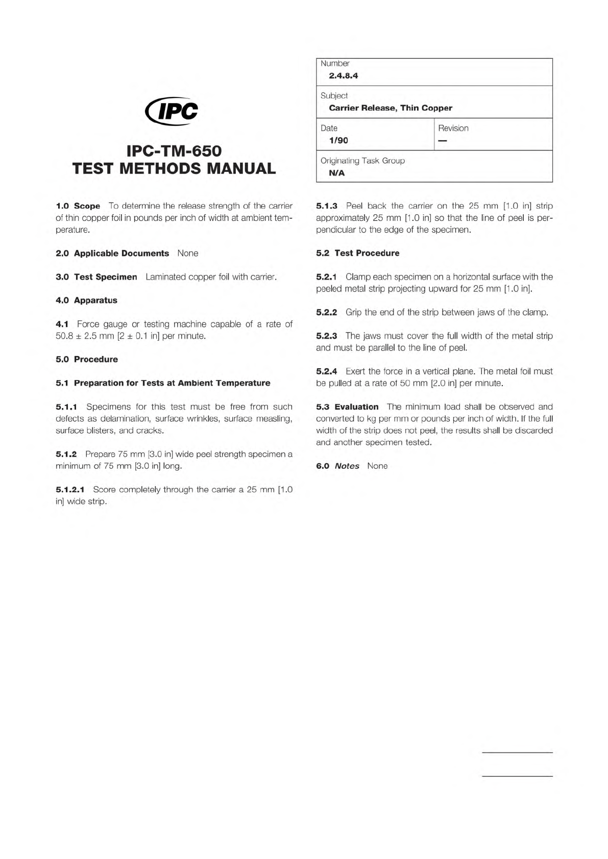
3.1 Type A – Etched Specimen
3.1.1
The test specimen consist of an etched conduc-
tor pattern in accordance with Figure 1.
Conductors
are 3.2 mm wide by 228.6 mm long [0.125 in wide by
9 in long].
3.1.2
A minimum of four specimens, two from the machine
direction (MD) and two from the transverse direction (TD),
be prepared for each of the procedure Methods A, C,
E. If a statistically sound evaluation by a given supplier can
prove that MD and TD measurements differ, the direction giv-
ing the lower measurement can be the only direction tested. If
the two directions are the same, only the MD direction needs
to be tested. In the event a test specimen tears during test-
ing, another test specimen will be prepared to replace it.
3.1.3
For double clad laminate, a separate sample unit
be prepared and tested for each side.
3.2 Type B – Die Cut Specimen
3.2.1
The test specimen consist of a strip of clad flex-
ible material 12.7 mm wide by 228.6 mm long [1/2 in wide by
9 in long].
3.2.2
A minimum of four specimens, two from the machine
direction and two from the transverse direction,
be pre-
pared for each of the procedure Methods B, D, F. If a statis-
tically sound evaluation by a given supplier can prove that MD
and TD measurements differ, the direction giving the lower
measurement can be the only direction tested. If the two
directions are the same, only the MD direction needs to be
tested.
3.2.3
For double clad laminate, a separate sample unit
be prepared and tested for each side. The metal foil on the
non-test side may remain to provide stability to prevent tent-
ing of the specimen from the German Wheel (free wheel rotary
drum). Both samples must be the same with respect to being
with or without the non-test side metal foil.
4 Test Equipment
4.1 Testing Machine
Power driven testing machine,
crosshead autographic type, or an equivalent constant speed
drive machine.
4.2 Sample Cutter
Thwing Albert sample cutter, Model
No. JDC-50, or equivalent.
4.3 Test Fixture
Free wheeling rotary drum (Figure 2), slid-
ing plate (Figure 3), or equivalent. The referee fixture will be a
152.4 mm [6.0 in] diameter free wheeling rotary drum.
IPC-249-1
▼
▼
▼
▼
3000 Lakeside Drive, Suite 309S
Bannockburn, IL 60015-1249
IPC-TM-650
TEST METHODS MANUAL
Number
2.4.9
Subject
Peel Strength, Flexible Dielectric Materials
Date
04/14
Revision
E
Originating Task Group
Flexible Circuits Test Methods Subcommittee
(D-15)
Association
Connecting
Electronics
Industries
shall
shall
Note:
shall
shall
shall
3.2mm
[0.125"]
Figure
1
Type
A
Peel
Strength
Test
Pattern
228.6mm
-
[9"]
-
Material
/n
this
Test
Methods
Manual
was
voluntarily
established
by
Technical
Committees
of
I
PC.
This
material
/s
advisory
only
and
"s
use
or
adaptation
,
s
entirely
voluntary.
IPC
disclaims
all
liability
of
any
kind
as
to
the
use,
application,
or
adaptation
of
this
material.
Users
are
also
wholly
responsible
for
protecting
themselves
against
all
claims
or
liabilities
for
patent
infringement.
Equipment
referenced
/s
for
the
convenience
of
the
user
and
does
not
imply
endorsement
by
IPC.
Page
1
of
6
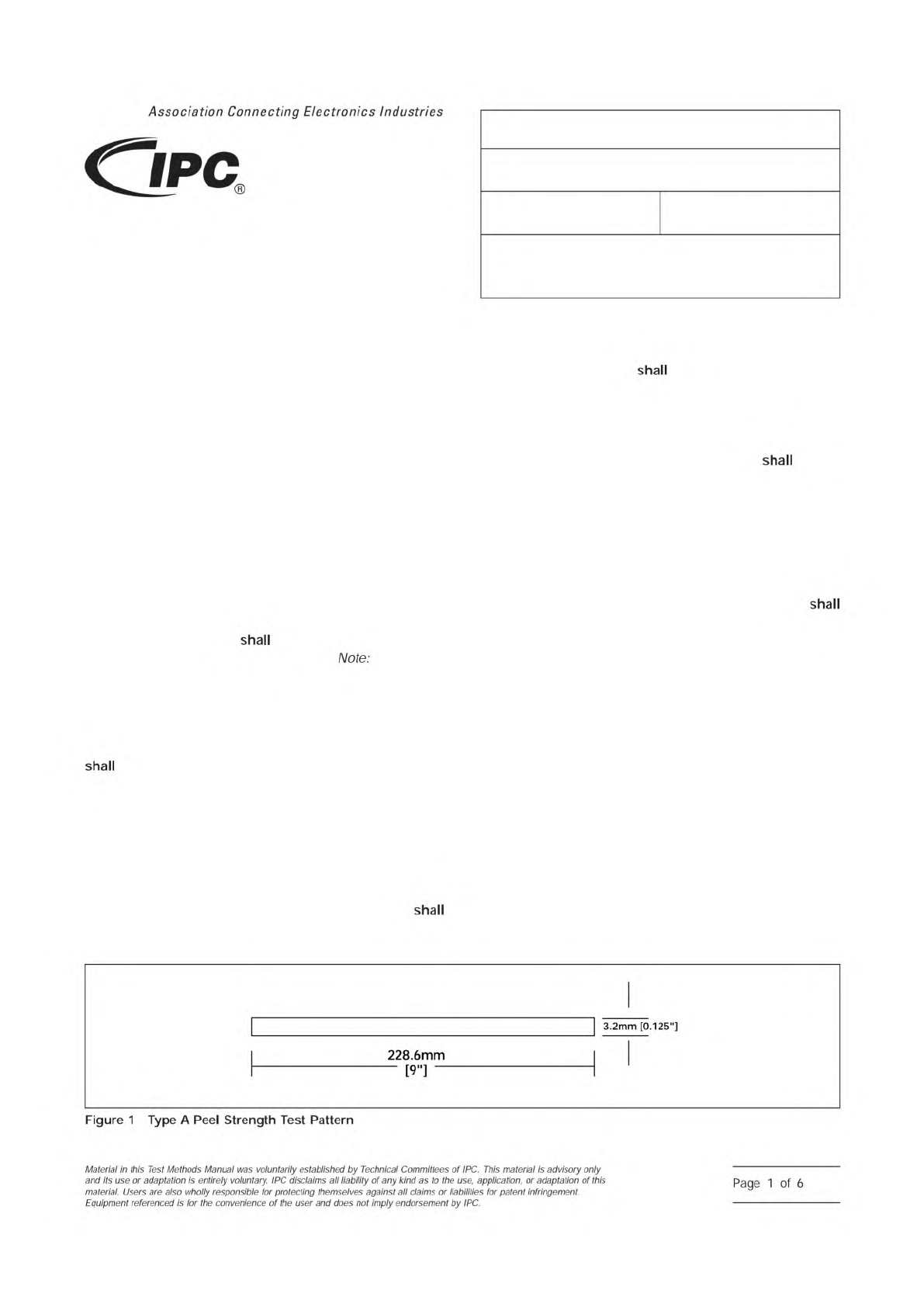
Figure 7 Corners Supports
R1 R1
R2
Supporting Jacks or Blocks
Figure 8 Highest Point Measurement
Measure at
This Point
Measure at
This Point
R2
R2
R1
IPC-TM-650
Page 5 of 5
Number
2.4.22
Subject
Bow
and
Twist
(Percentage)
Date
6/99
Revision
C
///////////
//////
/
/////////
I
PC-2422-7
I
PC-2422-8