IPC-TM-650 EN 2022 试验方法--.pdf - 第613页
Figure 3 Four Probe Interconnect R esistance Measurement T echn ique f or Flex to PWB and Flex to ITO Glass VI Ih, Vh I1 R1= AV/I 6th tra ce Figure 2 Interconnection Resi stan ce T es t Assembly; Flex to PWB 0.4 mm Flex,…
IPC-TM-650
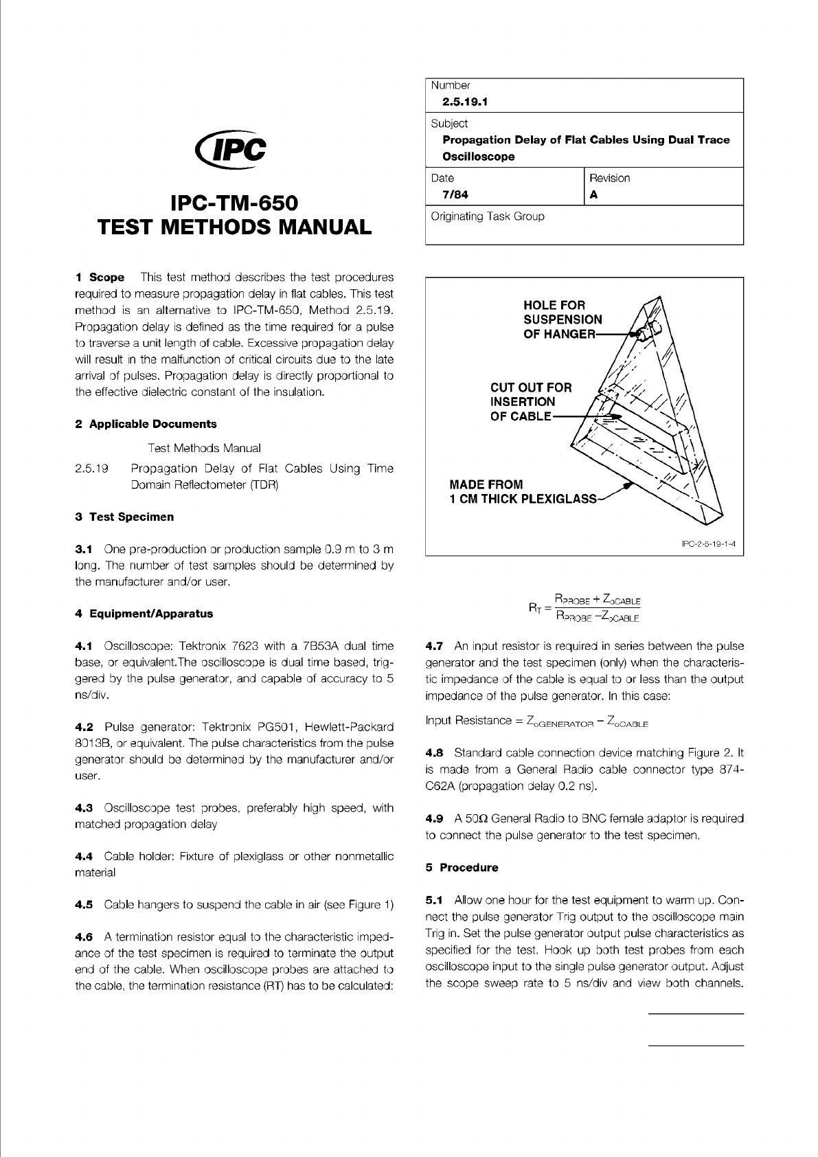
Figure 1 Sample Cable Hanger
The Institute for Interconnecting and Packaging Electronic Circuits
2215 Sanders Road • Northbrook, IL 60062
Material in this Test Methods Manual was voluntarily established by Technical Committees of the IPC. This material is advisory only
and its use or adaptation is entirely voluntary. IPC disclaims all liability of any kind as to the use, application, or adaptation of this
material. Users are also wholly responsible for protecting themselves against all claims or liabilities for patent infringement.
Equipment referenced is for the convenience of the user and does not imply endorsement by the IPC.
Page 1 of 4
IPC-TM-650
TEST
METHODS
MANUAL
1
Scope
This
test
method
describes
the
test
procedures
required
to
measure
propagation
delay
in
flat
cables.
This
test
method
is
an
alternative
to
IPC-TM-650,
Method
2.5.1
9.
Propagation
delay
is
defined
as
the
time
required
for
a
pulse
to
traverse
a
unit
length
of
cable.
Excessive
propagation
delay
will
result
in
the
malfunction
of
critical
circuits
due
to
the
late
arrival
of
pulses.
Propagation
delay
is
directly
proportional
to
the
effective
dielectric
constant
of
the
insulation.
2
Applicable
Documents
Test
Methods
Manual
2
.5.19
Propagation
Delay
of
Flat
Cables
Using
Time
Domain
Reflectometer
(TDR)
3
Test
Specimen
3.1
One
pre-production
or
production
sample
0.9
m
to
3
m
long.
The
number
of
test
samples
should
be
determined
by
the
manufacturer
and/or
user.
4
Equipment/Apparatus
4.1
Oscilloscope:
Tektronix
7623
with
a
7B53A
dual
time
base,
or
equivalent.The
oscilloscope
is
dual
time
based,
trig¬
gered
by
the
pulse
generator,
and
capable
of
accuracy
to
5
ns/div.
4.2
Pulse
generator:
Tektronix
PG501
,
Hewlett-Packard
801
3B,
or
equivalent.
The
pulse
characteristics
from
the
pulse
generator
should
be
determined
by
the
manufacturer
and/or
user.
4.3
Oscilloscope
test
probes,
preferably
high
speed,
with
matched
propagation
delay
4.4
Cable
holder:
Fixture
of
plexiglass
or
other
nonmetallic
material
4.5
Cable
hangers
to
suspend
the
cable
in
air
(see
Figure
1)
4.6
A
termination
resistor
equal
to
the
characteristic
imped¬
ance
of
the
test
specimen
is
required
to
terminate
the
output
end
of
the
cable.
When
oscilloscope
probes
are
attached
to
the
cable,
the
termination
resistance
(RT)
has
to
be
calculated:
Number
2.5.19.1
Subject
Propagation
Delay
of
Flat
Cables
Using
Dual
Trace
Oscilloscope
Date
Revision
7/84
A
Originating
Task
Group
R
_
RpROBE
+
ZoCABLE
RpROBE
-ZqcaBLE
4.7
An
input
resistor
is
required
in
series
between
the
pulse
generator
and
the
test
specimen
(only)
when
the
characteris¬
tic
impedance
of
the
cable
is
equal
to
or
less
than
the
output
impedance
of
the
pulse
generator.
In
this
case:
Input
Resistance
=
ZoGENERATOR
-
ZoCABLE
4.8
Standard
cable
connection
device
matching
Figure
2.
It
is
made
from
a
General
Radi。
cable
connector
type
874-
C62A
(propagation
delay
0.2
ns).
4.9
A
50Q
General
Radio
to
BNC
female
adaptor
is
required
to
connect
the
pulse
generator
to
the
test
specimen.
5
Procedure
5.1
Allow
one
hour
for
the
test
equipment
to
warm
up.
Con¬
nect
the
pulse
generator
Trig
output
to
the
oscilloscope
main
Trig
in.
Set
the
pulse
generator
output
pulse
characteristics
as
specified
for
the
test.
Hook
up
both
test
probes
from
each
oscilloscope
input
to
the
single
pulse
generator
output.
Adjust
the
scope
sweep
rate
to
5
ns/div
and
view
both
channels.
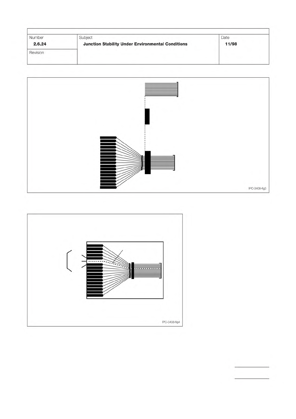
Figure 3 Four Probe Interconnect Resistance Measurement Technique for
Flex to PWB and Flex to ITO Glass
VI
Ih, Vh
I1
R1= AV/I
6th trace
Figure 2 Interconnection Resistance Test Assembly; Flex to PWB
0.4 mm Flex, Shortened on End
17 Traces, 9 mm x 25 mm
ZAF, 0.050 mm, 3.2 mm x 10 mm
Bonded Test Sample
0.2 mm line/space
Pitch Flex Board
IPC-TM-650
Page 3 of 3
Number
2.6.24
Subject
Junction
Stability
Under
Environmental
Conditions
Date
11/98
Revision
IPC-3408-fig3
IPC-3408-fig4
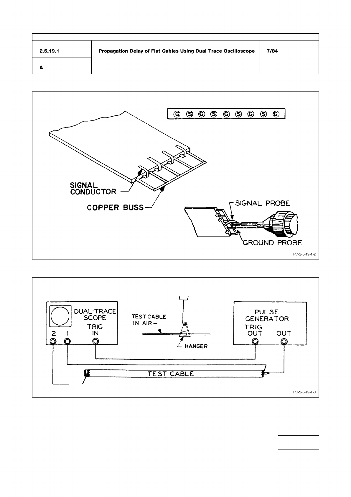
Figure 3 Cable Preparation and Cable Connection
Figure 4 Test Cable Hookup
IPC-TM-650
Number
Subject Date
Revision
Page 3 of 4
2.5.19.1
Propagation
Delay
of
Flat
Cables
Using
Dual
Trace
Oscilloscope
7/84
A
IPC-2-5-19-1-3