IPC-TM-650 EN 2022 试验方法--.pdf - 第660页
Figure 3 Vibration T es t Curves IPC-TM-650 Page 4 of 6 .0001 .00005 - .00001 10 L000 2,000 10.000 VIBRATION FREQUENCY (CPS) Number 3.12 Subject Vibration, Connectors Date 7/75 Revision A 1 00 ^§5^ &mno £ wwldwv NOUV…
1 Scope
This test method is used to determine the mois-
ture and insulation resistances of applied polymer solder mask
under two separate prescribed conditions of temperature and
humidity. One condition is described as Class T and the other
Class H. Raw material qualification testing is performed on
designated comb patterns. Production quality conformance
testing is performed on a standard ‘‘Y’’ pattern.
2 Applicable Documents
Multipurpose One-Sided Test Pattern -
Gerber Format
Qualification and Performance of Permanent
Solder Mask
Requirements for Soldering Fluxes
Acceptability for Printed Boards
3 Test Specimens
The IPC-A-25A-G-KIT artwork package
provides the Gerber files necessary for the fabrication of the
standard IPC-B-25A test board used with this test method.
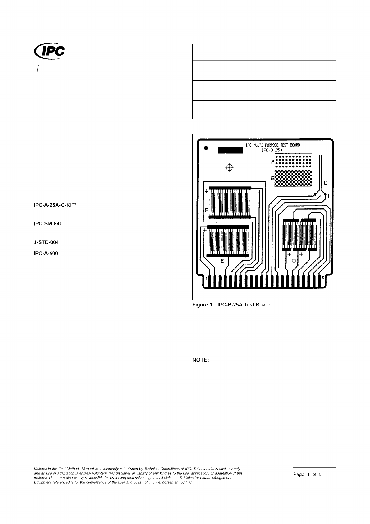
3.1 Qualification Testing
3.1.1 Class H
Three IPC-B-25A boards using the D comb
patterns with 0.32 mm [0.0126 in] lines/spaces (see Figure 1).
Of which, two are to be coated and one uncoated with solder
mask according to the solder mask supplier’s recommenda-
tions.
3.1.2 Class T
Three IPC-B-25A boards using the E and F
comb patterns with 0.41 mm [0.016 in] lines and 0.51 mm
[0.020 in] spaces (see Figure 1). Of which, two are to be
coated and one uncoated with solder mask according to the
solder mask supplier’s recommendations.
3.2 Conformance Testing
IPC-B-25A board C (‘‘Y’’
shape) pattern with 0.64 mm lines/0.64 mm spacing [0.025 in
lines/0.025 in spacing] or pattern with minimum spacing on
the production board (see Figure 1), whichever has the small-
est line spacing, coated with solder mask according to the
solder mask suppliers recommendations.
4 Apparatus
4.1 Chamber
A clean chamber capable of programming
and recording an environment of 25 ± 2 °C [77 ± 3.6 °F] to at
least 65 ± 2 °C [149 ± 3.6 °F] and 90-98% relative humidity.
This test requires a clean chamber and clean water
for repeatable test results. The following recommendations
are made:
• Incoming water purity should be between 0.5 and 0.1
micro-siemens/cm.
• Fresh deionized water should be used for each test, rather
than using a recirculating water sump.
• Chamber workspaces should be cleaned at least every six
months.
1. www.ipc.org/onlinestore
IPC-2631-1
3000 Lakeside Drive, Suite 309S
Bannockburn, IL 60015-1249
IPC-TM-650
TEST METHODS MANUAL
Number
2.6.3.1
Subject
Solder Mask - Moisture and Insulation Resistance
Date
03/07
Revision
E
Originating Task Group
Solder Mask Performance Task Group (5-33b)
ASSOCIATION CONNECTING
ELECTRONICS INDUSTRIES
®
IPC-A-25A-G-KIT1
IPC-SM-840
J-STD-004
IPC-A-600
Figure
1
IPC-B-25A
Test
Board
NOTE:
Material
in
this
Test
Methods
Manual
was
voluntarily
established
by
Technical
Committees
of
IPC.
material
advisory
only
and
its
use
or
adaptation
,
s
entirely
voluntary.
IPC
disclaims
all
liability
of
any
kind
as
to
the
use,
application,
or
adaptation
of
this
material.
Users
are
also
wholly
responsible
for
protecting
themselves
against
all
claims
or
liabilities
for
paten!
infringement.
Equipment
referenced
/s
the
convenience
of
the
user
and
does
not
imply
endorsement
by
IPC.
Page
1
of
5
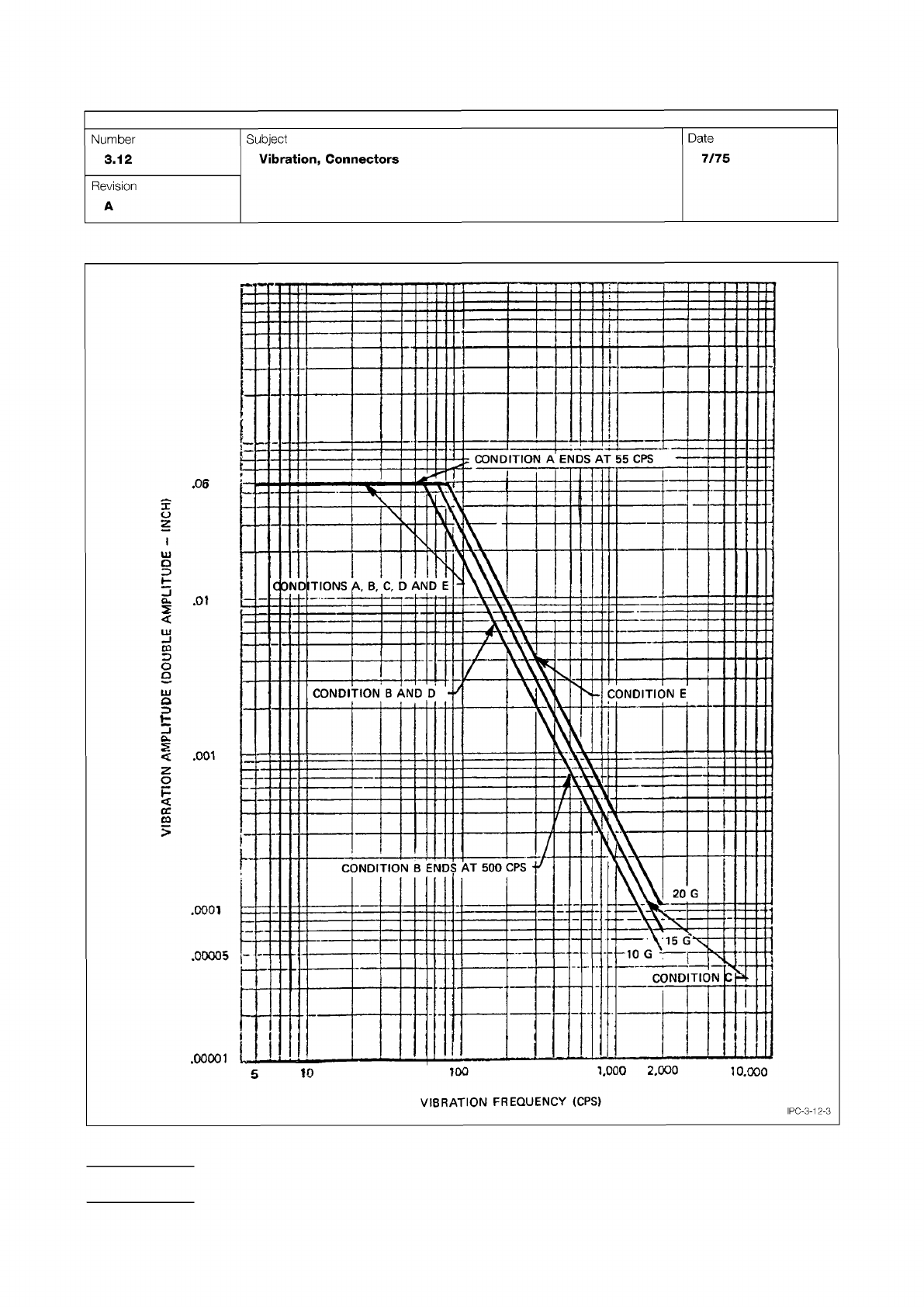
Figure 3 Vibration Test Curves
IPC-TM-650
Page 4 of 6
.0001
.00005
-
.00001
10
L000
2,000
10.000
VIBRATION
FREQUENCY
(CPS)
Number
3.12
Subject
Vibration,
Connectors
Date
7/75
Revision
A
1
00
^§5^
&mno
£
wwldwv
NOUVH
-
A
IPC-3-12-3
5.7.1.1
Place specimens in a chamber, in a vertical position
and under a condensation drip shield. Condition the speci-
mens at 50 ± 2 °C [122 ± 3.6 °F] with no added humidity, for
a period of 24 hours.
5.7.1.2
Allow the specimens to cool, measure and record
the initial insulation resistance measurements at ambient labo-
ratory conditions. Apply 100 VDC on the specimen’s test
points as specified in 3.1.1 or 3.2 with the resistance meter
and take the reading after one minute. See 6.2.
5.7.1.3
Connect the 50 VDC voltage source to each of the
specimens test points as indicated in 3.1.1 or 3.2. Each
chamber load shall contain at least one uncoated control
board that is representative of the cleaning process used prior
to solder mask application for each solder mask tested.
5.7.1.4
The test points for qualification tests are 1 to 2, 3 to
2, 3 to 4 and 5 to 4 on the D comb pattern. On the D comb
pattern, test points 1, 3 and 5 are connected to the positive
terminal and test points 2 and 4 are connected to the nega-
tive terminal of the resistance meter. For quality conformance,
the pair of test points is 1 to 2 on the C pattern. One side of
the C pattern should be connected to the negative terminal
and the other side to the positive.
5.7.1.5
Close chamber door and apply a 50 volt bias to all
comb patterns (D or C patterns) tested.
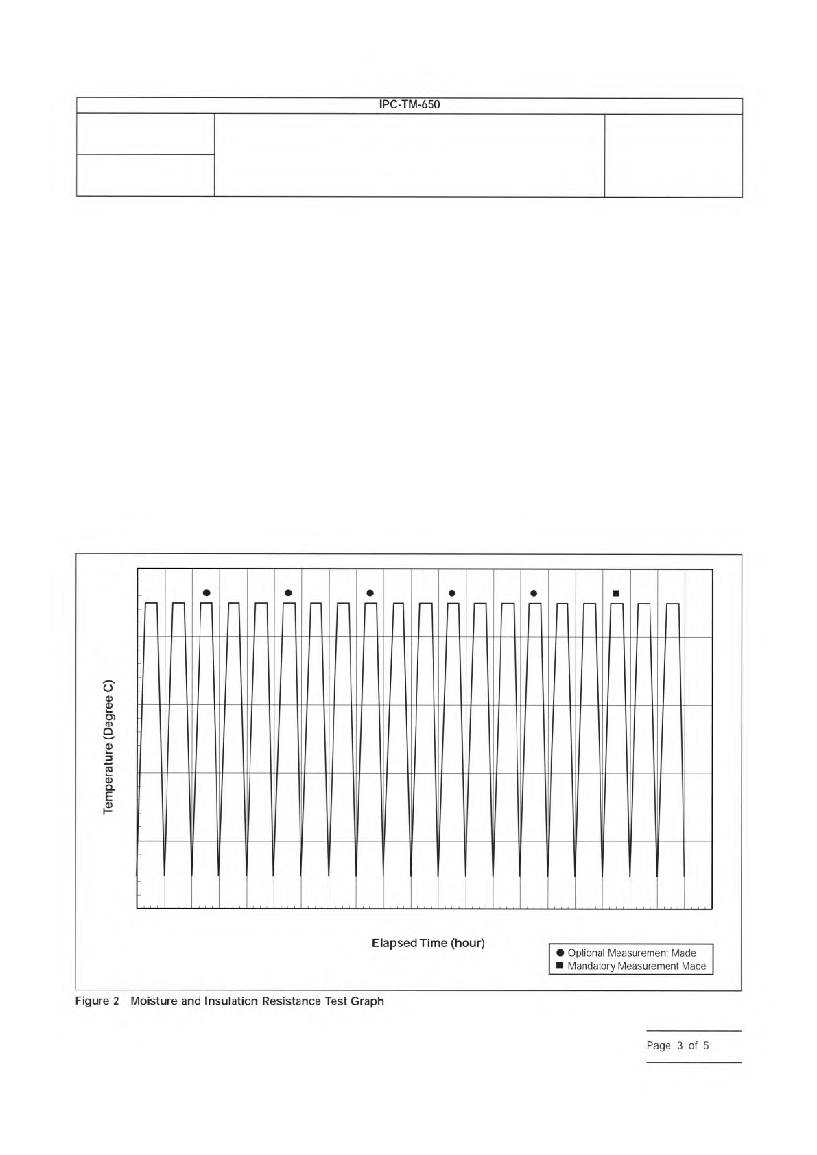
5.7.1.6
Expose test specimens to 20 cycles of temperature
and humidity (see Figure 2). The bias voltage shall be main-
tained throughout the entire 20-cycle period. Humidity shall be
maintained at 85% minimum through the cycles except when
going to low temperature (see step c below), in which case
the humidity may temporarily drop to 80% minimum.
One cycle is as follows:
a. Start test at 25 ± 2 °C [77 ± 3.6 °F] and raise the tempera-
ture to 65 ± 2 °C [149 °F] over a time span of 2.5 hours ±
5 minutes
0
20
30
40
50
60
70
8 16 24 32 40 48 56 64 72 80 88 96 104 112 120 128 136 144 152 160 168
Number
2.6.3.1
Subject
Solder Mask - Moisture and Insulation Resistance
Date
03/07
Revision
E
Elapsed
Time
(hour)
•
Optional
Measurement
Made
Mandatory
Measurement
Made
IPC-TM-650
—
6
dE
Figure
2
Moisture
and
Insulation
Resistance
Test
Graph
Page
3
of
5