IPC-TM-650 EN 2022 试验方法--.pdf - 第99页
IPC-TM-650 Number Subject Date Revision Page 2 of 2 2.2.18 Determination of Thickness of Laminates by Mechanical Measurement 12/94 5.3.2.2.2.1 Calculate the overall nominal thickness by add¬ ing to the base nominal thick…
The Institute for Interconnecting and Packaging Electronic Circuits
2215 Sanders Road • Northbrook, IL 60062
Material in this Test Methods Manual was voluntarily established by Technical Committees of the IPC. This material is advisory only
and its use or adaptation is entirely voluntary. IPC disclaims all liability of any kind as to the use, application, or adaptation of this
material. Users are also wholly responsible for protecting themselves against all claims or liabilities for patent infringement.
Equipment referenced is for the convenience of the user and does not imply endorsement by the IPC.
Page 1 of 2
IPC-TM-650
TEST
METHODS
MANUAL
Number
2.2.18
Subject
Determination
of
Thickness
of
Laminates
by
Mechanical
Measurement
Date
Revision
12/94
Originating
Task
Group
MIL-P-13949
Test
Methods
Task
Group
(7-1
1b)
1
.0
Scope
This
test
method
is
designed
to
determine
the
thickness
of
unclad
or
metallic
clad
laminate,
with
or
without
the
cladding,
using
mechanical
measurements.
2
.0
Applicable
Documents
IPC-TM-650
Method
2.3.6,
Etching,
Ammonium
Persulfate
Method
2.3.7,
Etching,
Ferric
Chloride
Method
2.3.
7.1,
Cupric
Chloride
Etching
Method
2.3.
7.2,
Alkaline
Etching
3
.0
Test
Specimens
Consult
with
the
applicable
specifica¬
tion
for
size
or
configuration,
quantity,
and
location
taken
from
the
laminate.
3.1
Size
Test
specimens
may
be
strips
cut
from
the
lami¬
nate
and
shall
be
12.7
mm
[0.5
in]
wide,
minimum.
Sheets
or
cut-to-size
panels
may
be
used
as
specimens.
3.2
Sampling
Unless
otherwise
specified,
two
specimens
shall
be
taken
from
locations
within
the
sampling
that
repre¬
sent
the
centermost
area
and
the
edges,
but
no
closer
than
25.4
mm
[1
.0
in]
from
the
edge,
of
the
as-
manufactured
sheet.
4
.0
Apparatus
or
Material
4.1
Micrometer
with
a
minimum
throat
depth
of
25.4
mm
[1
.0
in]
and
with
accuracy
of
0.0025
mm
[0.0001
in],
or
equivalent.
4.2
Etching
system
capable
of
complete
removal
of
metallic
cladding.
IPO
Test
Methods
2.3.6, 2.3.7,
2.3.7.
1
,
or
2.37.2
shall
be
used
for
referee
testing.
5
.0
Procedure
5.1
Specimen
Preparation
5.1.1
Method
A,
Metallic
Cladding
Removed
This
method
is
used
to
determine
base
laminate
thickness
by
direct
measurement
of
the
laminate
without
cladding.
It
shall
be
used
for
qualification
or
referee
testing.
5.1.
1.1
Completely
etch
the
test
specimen
in
accordance
with
accepted
industry
practices.
5.1.2
Method
B,
As
Manufactured
This
method
is
used
to
determine
overall
thickness
of
unclad
or
metallic
clad
lami¬
nates.
It
is
used
to
determine
base
thickness
of
metallic
clad
laminates
when
evaluated
in
accordance
with
5.3.222.
Unless
otherwise
specified,
it
shall
be
used
for
product
accep¬
tance
inspection.
5.1
.2.1
The
specimens
shall
be
tested
in
the
as-
manufactured
condition.
5.2
Measurements
Using
the
micrometer,
determine
the
thickness
of
the
specimen.
Unless
otherwise
specified,
speci¬
mens
that
are
sheets
or
panels
shall
be
measured
at
least
25.4
mm
[1
.0
in]
from
the
edge
at
all
four
(4)
corners.
5.3
Evaluation
5.3.1
Data
Recording
For
purposes
including
qualification
or
referee
testing,
product
evaluation,
statistical
analysis,
etc.,
each
thickness
measurement
shall
be
recorded,
unless
other¬
wise
specified.
5.3.2
Compliance
to
Specification
5.3.2.1
Unclad
laminates
or
metallic
clad
laminates
with
overall
nominal
thickness
Measurements
taken
after
specimen
preparation
per
5.1
.2
shall
be
compared
with
the
applicable
specification
for
compliance
to
the
required
toler¬
ances.
5.3.
2.2
Metallic
Clad
Laminates
with
Base
Nominal
Thickness
5.3.2.2.1
Compliance
to
Specification
Using
Method
A
Specimen
Preparation
Measurements
taken
after
speci¬
men
preparation
per
5.1.1
shall
be
compared
with
the
appli¬
cable
specification
for
compliance
to
the
required
tolerances.
5.3.2.2.2
Compliance
to
Specification
Using
Method
B
Specimen
Preparation
IPC-TM-650
Number
Subject Date
Revision
Page 2 of 2
2.2.18
Determination
of
Thickness
of
Laminates
by
Mechanical
Measurement
12/94
5.3.2.2.2.1
Calculate
the
overall
nominal
thickness
by
add¬
ing
to
the
base
nominal
thickness
the
total
thickness
of
the
metallic
cladding.
Thickness
of
metallic
cladding
shall
be
based
on
.035
mm
[0.0014
in]
per
45.7
g
[1.0
oz],
or
as
sup¬
plied
by
the
foil
supplier.
5.3.2.2.2.2
Calculate
the
minimum
and
maximum
limits
by
subtracting
and
adding
the
required
tolerance
from
the
over¬
all
nominal
thickness.
5.3.2.2.2.3
Measurements
taken
after
specimen
prepara¬
tion
per
5.1
.2
shall
be
compared
with
the
minimum
and
maxi¬
mum
limits
as
determined
in
5.
3.2.2.
2.
5.4
Report
Unless
otherwise
specified,
report
the
average,
minimum
and
maximum
readings,
and
compliance
with
requirements,
if
applicable.
6.0
Notes
6.1
Use
of
hand
or
manual
micrometers
should
be
carefully
administered.
Pressure,
anvil
shape,
and
other
features
of
the
micrometer
and
its
use
must
follow
accepted
industry
practices,
if
not
defined
in
the
applicable
specification.
IPC-TM-650
IPC-TM-650
The Institute for Interconnecting and Packaging Electronic Circuits
2215 Sanders Road • Northbrook, IL 60062
Material in this Test Methods Manual was voluntarily established by Technical Committees of the IPC. This material is advisory only
and its use or adaptation is entirely voluntary. IPC disclaims all liability of any kind as to the use, application, or adaptation of this
material. Users are also wholly responsible for protecting themselves against all claims or liabilities for patent infringement.
Equipment referenced is for the convenience of the user and does not imply endorsement by the IPC.
Page 1 of 1
IPC-TM-650
TEST
METHODS
MANUAL
1
.0
Scope
This
test
method
is
designed
to
determine
the
minimum
and
maximum
thickness
of
the
base
material
of
metallic
clad
laminates
by
microsectioning
and
optical
mea¬
surement.
2
.0
Applicable
Documents
Method
2.1
.1
,
Microsectioning
Method
2.2.18,
Determination
of
Thickness
of
Laminates,
by
Mechanical
Measurement
3
.0
Test
Specimens
3.1
Size
Unless
otherwise
specified,
a
specimen
measuring
25.4
X
12.7
mm
[1.0
X
0.5
in]
shall
be
taken
from
the
laminate
sample.
3.2
Quantity
and
Sampling
Unless
otherwise
specified,
two
samples
shall
be
taken
from
the
lot
that
represent
the
centermost
area
and
the
edges,
but
no
closer
than
25.4
mm
[1
.0
in]
from
the
edge,
of
the
as-
manufactured
sheet.
4
.0
Apparatus
or
Material
4.1
Any
optical
inspection
measuring
device
with
a
capabil¬
ity
of
1
00X
and
200X
with
an
accuracy
to
0.0025
mm
[0.0001
in].
4.2
A
microsectioning
system
capable
of
preparing
speci¬
men
mounts
that
can
be
used
for
this
procedure.
5
.0
Procedure
5.1
Preparation
of
Specimens
Each
specimen
to
be
measured
shall
be
microsectioned
in
accordance
with
IPC-
TM-650,
Method
2.1.1
.
The
long
dimension
of
the
specimen
shall
be
in
the
plane
of
examination.
Specimens
may
be
ganged
in
accordance
with
the
sampling
procedure.
5.2
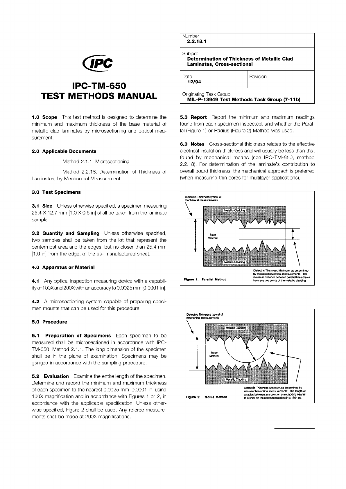
Evaluation
Examine
the
entire
length
of
the
specimen.
Determine
and
record
the
minimum
and
maximum
thickness
of
each
specimen
to
the
nearest
0.0025
mm
[0.0001
in]
using
100X
magnification
and
in
accordance
with
Figures
1
or
2,
in
accordance
with
the
applicable
specification.
Unless
other¬
wise
specified,
Figure
2
shall
be
used.
Any
referee
measure¬
ments
shall
be
made
at
200X
magnifications.
Number
2.2.18.1
Subject
Determination
of
Thickness
of
Metallic
Clad
Laminates,
Cross-sectional
Date
12/94
Revision
Originating
Task
Group
MIL-P-13949
Test
Methods
Task
Group
(7-1
1b)
5.3
Report
Report
the
minimum
and
maximum
readings
found
from
each
specimen
inspected,
and
whether
the
Paral¬
lel
(Figure
1)
or
Radius
(Figure
2)
Method
was
used.
6
.0
Notes
Cross-sectional
thickness
relates
to
the
effective
electrical
insulation
thickness
and
will
usually
be
less
than
that
found
by
mechanical
means
(see
IPC-TM-650,
method
2.2.18).
For
determination
of
the
laminate's
contribution
to
overall
board
thickness,
the
mechanical
approach
is
preferred
(when
measuring
thin
cores
for
multilayer
applications).
minimum
distance
between
parallel
lines
drawn
from
any
two
points
of
the
metallic
cladding
Dielectric
Thickness
typical
of
mechanical
measurements
Figure
1:
Parallel
Method
Dielectric
Thickness
typical
of
Figure
2:
Radius
Method
a
radius
between
any
point
on
one
cladding
nearest
to
a
point
on
the
opposite
cladding
in
a
180°
arc.