IPC-TM-650 EN 2022 试验方法--.pdf - 第702页
IP C- T -5 0 IPC-CH-65 J-STD-001 IE C - TC - 9 1 The Institute for Int erconnecting and Packaging E lectronic Circuits 2215 S anders Road • Northbrook, IL 60062-6135 Material in this T est M ethods Manual was vol untaril…
IPC-6012
Material in this Test Methods Manual was voluntarily established by Technical Committees of IPC. This material is advisory only
and its use or adaptation is entirely voluntary. IPC disclaims all liability of any kind as to the use, application, or adaptation of this
material. Users are also wholly responsible for protecting themselves against all claims or liabilities for patent infringement.
Equipment referenced is for the convenience of the user and does not imply endorsement by IPC.
Page 1 of 1
ASSOCIATION
CONNECTING
/
ELECTRONICS
INDUSTRIES
®
221
5
Sanders
Road
Northbrook,
IL
60062-6135
IPC-TM-650
TEST
METHODS
MANUAL
1
Scope
This
test
describes
a
procedure
which
may
be
conducted
to
determine
if
a
printed
wiring
board
is
con¬
structed
to
withstand
the
dynamic
vibrational
stresses
that
may
be
encountered
during
field
service.
This
test
method
provides
specific
parameters
for
one
application
in
order
to
present
the
proper
procedures.
Specific
test
conditions
must
be
agreed
upon
by
the
customer
and
the
vendor.
2
Applicable
Documents
Qualification
and
Performance
Specification
for
Rigid
Printed
Boards
3
Test
Specimen
The
preproduction
or
production
printed
wiring
board.
4
Apparatus
4.1
Vibration
A
vibration
system
capable
of
producing
an
input
of
25
G's
over
a
frequency
range
from
20
Hz
to
2000
Hz
to
20
Hz
performed
in
1
6
minutes.
4.2
Mounting
Fixtures
4.3
The
test
fixture
must
be
designed
such
that
resonant
vibration
inherent
in
the
fixture
within
the
frequency
range
specified
for
the
test
shall
be
minor.
The
magnitude
of
the
applied
vibration
should
be
monitored
on
the
test
fixture
near
the
specimen
mounting
points.
Number
2.6.9
Subject
Vibration,
Rigid
Printed
Wiring
Date
Revision
05/04
B
Originating
Task
Group
Rigid
Printed
Board
Performance
Task
Group
(D-33a)
4.4
The
test
specimen
shall
be
restrained
from
movement
by
fixturing
at
all
four
edges
and
with
the
flat
surface
of
the
boards
mounted
perpendicular
to
the
axis
of
vibration.
5
Test
Procedures
5.1
The
boards
shall
successfully
pass
the
interconnection
resistance
test
in
accordance
with
I
PC-60
12
before
and
after
the
vibration
test.
5.2
The
boards
shall
be
subjected
to
both
a
cycling
and
a
resonance
dwell
test.
5.2.1
The
cycling
test
shall
consists
of
one
sweep
from
20
Hz
to
2000
Hz
to
20
Hz
performed
in
16
minutes.
The
input
acceleration
(G's)
over
the
20-2000-20
Hz
frequency
range
shall
be
maintained
at
15
G's.
5.2.2
The
boards
shall
be
subjected
to
a
30-minute
reso¬
nance
dwell
with
25
G's
input
or
a
maximum
of
100
G's
out¬
put
measured
at
the
geometric
center
of
the
board.
5.3
Evaluation
Examine
boards
for
warp
or
delamination
and
interconnection
resistance
after
exposure
to
the
vibration
test.
6
Notes
None
IPC-T-50
IPC-CH-65
J-STD-001
IEC-TC-91
The Institute for Interconnecting and Packaging Electronic Circuits
2215 Sanders Road • Northbrook, IL 60062-6135
Material in this Test Methods Manual was voluntarily established by Technical Committees of the IPC. This material is advisory only
and its use or adaptation is entirely voluntary. IPC disclaims all liability of any kind as to the use, application, or adaptation of this
material. Users are also wholly responsible for protecting themselves against all claims or liabilities for patent infringement.
Equipment referenced is for the convenience of the user and does not imply endorsement by the IPC.
Page 1 of 5
IPC-TM-650
TEST
METHODS
MANUAL
Number
2.6.9.1
Subject
Test
to
Determine
Sensitivity
of
Electronic
Assemblies
to
Ultrasonic
Energy
Date
Revision
1/95
Originating
Task
Group
Ultrasonic
Cleaning
Task
Group
(5-31
e)
1
.0
Scope
The
purpose
of
this
test
method
is
to
provide
a
consistent
procedure
to
test
the
sensitivity
of
electronic
components
to
ultrasonic
energy.
There
has
been
a
reluctance
in
the
elec¬
tronics
industry
to
use
ultrasonic
energy
for
printed
board
assemblies
cleaning
because
of
the
possibility
of
damage
to
wire
bonds
in
active,
hermetically
sealed
components
or
other
damage
that
might
cause
latent
failures.
Recent
work
has
shown
that
electronic
components
have
a
low
potential
for
damage
from
ultrasonics
(See
6.1)
under
conditions
seen
in
most
cleaning
processes.
In
addition,
MIL-
STD-2000
Rev.
A
and
J
-STD
001
now
allow
for
the
use
of
ultrasonic
cleaning,
as
does
the
proposal
for
IEC
TC91
Inter¬
national
Standards
based
on
an
updated
revision
of
the
J-STD-001
.
1.1
Definitions
Ultrasound:
All
sound
in
frequencies
above
the
range
of
human
hearing.
For
the
purpose
of
ultrasonic
cleaning,
fre¬
quencies
between
1
8-800
kHz
are
in
commercial
use.
In
the
lower
frequency
ranges,
fluid
cavitation
is
the
primary
agitation
method.
In
the
higher
frequency
ranges,
microstreaming
(i.e.,
fluid
pumping)
is
believed
to
be
the
form
of
mechanical
agitation.
Frequency:
The
number
of
periodic
oscillations,
vibrations
of
waves
per
unit
of
time,
usually
expressed
in
cycles
per
sec¬
ond.
Generator:
An
electronic
system
which
converts
the
50
or
60
Hz
power
line
electricity
into
an
ultrasonic
frequency
drive
sig¬
nal
which
powers
the
transducers
in
their
resonant
frequency
range.
Transducers:
Convert
electrical
energy
from
the
generator
into
mechanical
(vibratory)
energy,
producing
high
intensity
sound
waves
in
a
liquid
and
causing
cavitation.
Transducers
are
pri¬
marily
of
two
types.
Piezoelectric:
Piezoelectric
ceramics,
which
change
dimen¬
sions
in
the
presence
of
an
electric
field.
Thickness
varies
in
response
to
an
applied
voltage.
Conversion
efficiency
=
70-90%
Magnetostrictive:
Made
of
nickel
or
its
alloys,
it
changes
length
when
placed
in
a
magnetic
field.
Conversion
efficiency
二
20-50%
Cavitation:
The
rapid
formation
and
oscillation
or
violent
col¬
lapse
of
microscopic
bubbles
or
cavities
in
a
liquid,
produced
by
introducing
high
frequency
(ultrasonic)
sound
waves
into
a
liquid.
The
agitation
from
countless
implosions
of
these
bubbles
create
a
highly
effective
scrubbing
of
both
exposed
and
hidden
surfaces
of
parts
immersed
in
the
cleaning
solution.
Degas:
The
act
of
removing
entrained
gas
from
cleaning
fluid.
Gas
bubbles
tend
to
absorb
ultrasonic
energy,
thereby
decreasing
the
amount
of
energy
available
for
cleaning.
2
.0
Applicable
Documents
2.1
Institute
for
Interconnecting
and
Packaging
Elec¬
tronic
Circuits
(IPC)
Terms
and
Definitions
for
Interconnecting
and
Packaging
Electronic
Assemblies
Guidelines
for
Cleaning
of
Printed
Boards
and
Assemblies
2.2
Joint
Industry
Standards
Requirements
for
Soldered
Electrical
and
Elec¬
tronic
Assemblies
2.3
Military
MIL-STD-2000
Rev.
A
Standard
Require¬
ments
for
Soldered
Electrical
and
Electronic
Assemblies
2.4
Other
Publications
Proposed
International
Standard
(based
on
J-STD-001)
International
Requirements
for
Soldered
Electrical
and
Electronic
Assemblies
Using
Surface
Mount
and
Related
Assembly
Technologies
3
.0
Test
Specimens
The
board
mounted
components
to
be
tested
should
be
the
exact
type
and
configuration
the
tester
intends
to
use
in
pro¬
duction.
A
statistically
valid
number
of
each
type
and
package
style
of
component
of
interest
should
be
tested.
For
example,
if
actual
production
boards
are
used
for
testing
and
only
one
of
a
particular
component
is
contained
on
the
board,
then
a
statistically
valid
number
of
boards
will
have
to
be
tested.
If,
instead
of
production
boards,
dummy
boards
are
used,
they
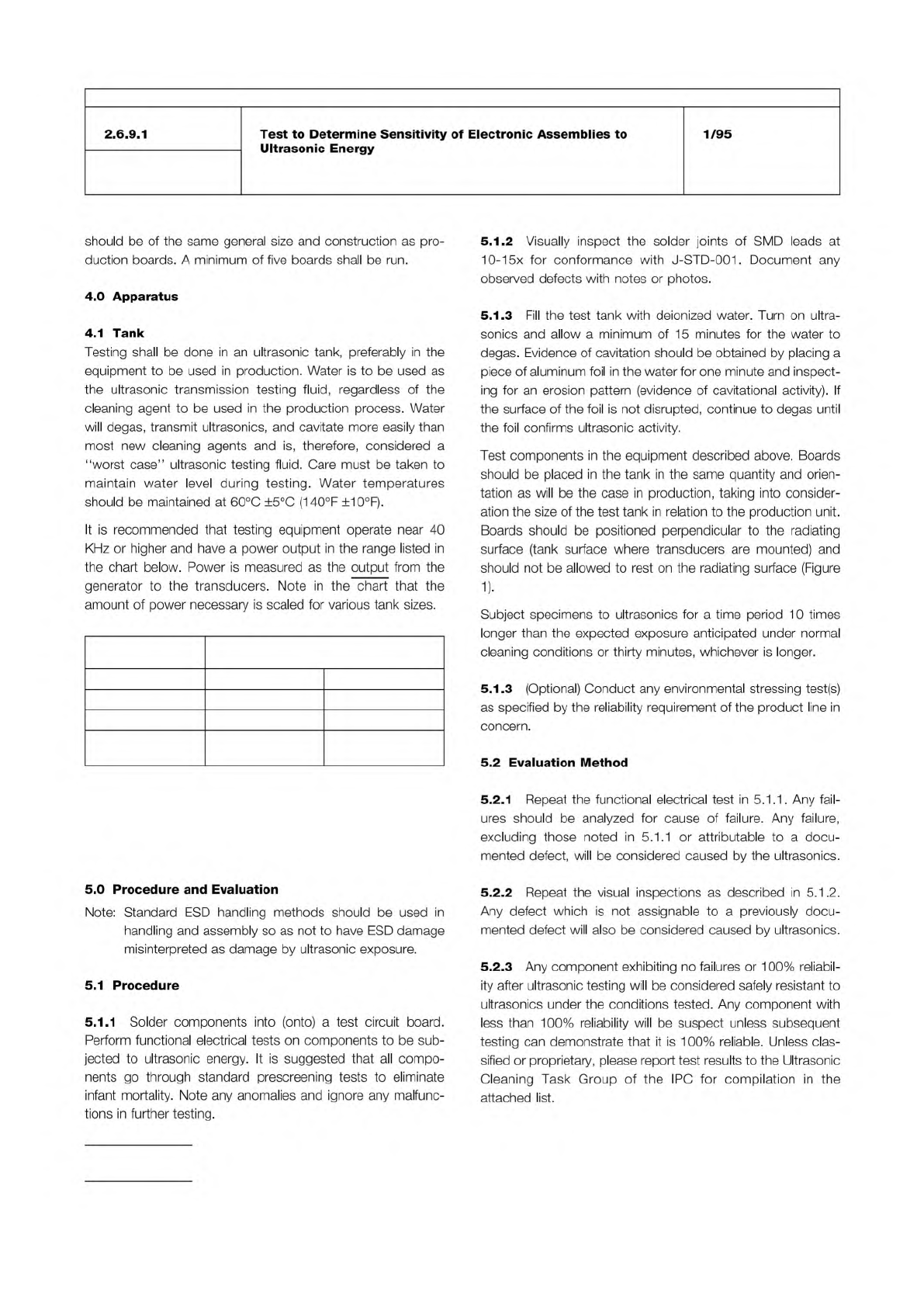
If power densities or frequencies differing from the
ranges listed above are to be used in production, they
should be used in testing as well, and noted on the
Ultrasonic Test Data Record.
Tank Size liters
(gallons)
Power Density
watts/liter(watts/gallon)
Magnetostrictive Piezoelectric
19 (5) 66-76 (250-290) 33-38 (125-145)
38 (10) 53-58 (200-220) 26.5-29 (100-110)
95 and greater (25
and greater)
21-32 (80-120) 10.5-16 (40-60)
IPC-TM-650
Number
Subject Date
Revision
Page 2 of 5
2.6.9.1
Test
to
Determine
Sensitivity
of
Electronic
Assemblies
to
Ultrasonic
Energy
1/95
should
be
of
the
same
general
size
and
construction
as
pro¬
duction
boards.
A
minimum
of
five
boards
shall
be
run.
4
.0
Apparatus
4.1
Tank
Testing
shall
be
done
in
an
ultrasonic
tank,
preferably
in
the
equipment
to
be
used
in
production.
Water
is
to
be
used
as
the
ultrasonic
transmission
testing
fluid,
regardless
of
the
cleaning
agent
to
be
used
in
the
production
process.
Water
will
degas,
transmit
ultrasonics,
and
cavitate
more
easily
than
most
new
cleaning
agents
and
is,
therefore,
considered
a
"worst
case”
ultrasonic
testing
fluid.
Care
must
be
taken
to
maintain
water
level
during
testing.
Water
temperatures
should
be
maintained
at
60℃
±5℃
(140°F
±10°F).
It
is
recommended
that
testing
equipment
operate
near
40
KHz
or
higher
and
have
a
power
output
in
the
range
listed
in
the
chart
below.
Power
is
measured
as
the
output
from
the
generator
to
the
transducers.
Note
in
the
chart
that
the
amount
of
power
necessary
is
scaled
for
various
tank
sizes.
5
.0
Procedure
and
Evaluation
Note:
Standard
ESD
handling
methods
should
be
used
in
handling
and
assembly
so
as
not
to
have
ESD
damage
misinterpreted
as
damage
by
ultrasonic
exposure.
5.1
Procedure
5.1.1
Solder
components
into
(onto)
a
test
circuit
board.
Perform
functional
electrical
tests
on
components
to
be
sub¬
jected
to
ultrasonic
energy.
It
is
suggested
that
all
compo¬
nents
go
through
standard
prescreening
tests
to
eliminate
infant
mortality.
Note
any
anomalies
and
ignore
any
malfunc¬
tions
in
further
testing.
5.1.2
Visually
inspect
the
solder
joints
of
SMD
leads
at
10-15x
for
conformance
with
J-STD-001
.
Document
any
observed
defects
with
notes
or
photos.
5.1.3
Fill
the
test
tank
with
deionized
water.
Turn
on
ultra¬
sonics
and
allow
a
minimum
of
1
5
minutes
for
the
water
to
degas.
Evidence
of
cavitation
should
be
obtained
by
placing
a
piece
of
aluminum
foil
in
the
water
for
one
minute
and
inspect¬
ing
for
an
erosion
pattern
(evidence
of
cavitational
activity).
If
the
surface
of
the
foil
is
not
disrupted,
continue
to
degas
until
the
foil
confirms
ultrasonic
activity.
Test
components
in
the
equipment
described
above.
Boards
should
be
placed
in
the
tank
in
the
same
quantity
and
orien¬
tation
as
will
be
the
case
in
production,
taking
into
consider¬
ation
the
size
of
the
test
tank
in
relation
to
the
production
unit.
Boards
should
be
positioned
perpendicular
to
the
radiating
surface
(tank
surface
where
transducers
are
mounted)
and
should
not
be
allowed
to
rest
on
the
radiating
surface
(Figure
1).
Subject
specimens
to
ultrasonics
for
a
time
period
10
times
longer
than
the
expected
exposure
anticipated
under
normal
cleaning
conditions
or
thirty
minutes,
whichever
is
longer.
5.1.3
(Optional)
Conduct
any
environmental
stressing
test(s)
as
specified
by
the
reliability
requirement
of
the
product
line
in
concern.
5.2
Evaluation
Method
5.2.1
Repeat
the
functional
electrical
test
in
5.1
.1
.
Any
fail¬
ures
should
be
analyzed
for
cause
of
failure.
Any
failure,
excluding
those
noted
in
5.1.1
or
attributable
to
a
docu¬
mented
defect,
will
be
considered
caused
by
the
ultrasonics.
5.2.2
Repeat
the
visual
inspections
as
described
in
5.1
.2.
Any
defect
which
is
not
assignable
to
a
previously
docu¬
mented
defect
will
also
be
considered
caused
by
ultrasonics.
5.2.3
Any
component
exhibiting
no
failures
or
1
00%
reliabil¬
ity
after
ultrasonic
testing
will
be
considered
safely
resistant
to
ultrasonics
under
the
conditions
tested.
Any
component
with
less
than
1
00%
reliability
will
be
suspect
unless
subsequent
testing
can
demonstrate
that
it
is
100%
reliable.
Unless
clas¬
sified
or
proprietary,
please
report
test
results
to
the
Ultrasonic
Cleaning
Task
Group
of
the
IPC
for
compilation
in
the
attached
list.