IPC-TM-650 EN 2022 试验方法--.pdf - 第704页
IPC-TM-650 Number Subject Date Revision Page 3 of 5 2.6.9.1 Test to Determine Sensitivity of Electronic Assemblies to Ultrasonic Energy 1/95 Note: It is important that the IPC receives as much data as possible, whether i…
If power densities or frequencies differing from the
ranges listed above are to be used in production, they
should be used in testing as well, and noted on the
Ultrasonic Test Data Record.
Tank Size liters
(gallons)
Power Density
watts/liter(watts/gallon)
Magnetostrictive Piezoelectric
19 (5) 66-76 (250-290) 33-38 (125-145)
38 (10) 53-58 (200-220) 26.5-29 (100-110)
95 and greater (25
and greater)
21-32 (80-120) 10.5-16 (40-60)
IPC-TM-650
Number
Subject Date
Revision
Page 2 of 5
2.6.9.1
Test
to
Determine
Sensitivity
of
Electronic
Assemblies
to
Ultrasonic
Energy
1/95
should
be
of
the
same
general
size
and
construction
as
pro¬
duction
boards.
A
minimum
of
five
boards
shall
be
run.
4
.0
Apparatus
4.1
Tank
Testing
shall
be
done
in
an
ultrasonic
tank,
preferably
in
the
equipment
to
be
used
in
production.
Water
is
to
be
used
as
the
ultrasonic
transmission
testing
fluid,
regardless
of
the
cleaning
agent
to
be
used
in
the
production
process.
Water
will
degas,
transmit
ultrasonics,
and
cavitate
more
easily
than
most
new
cleaning
agents
and
is,
therefore,
considered
a
"worst
case”
ultrasonic
testing
fluid.
Care
must
be
taken
to
maintain
water
level
during
testing.
Water
temperatures
should
be
maintained
at
60℃
±5℃
(140°F
±10°F).
It
is
recommended
that
testing
equipment
operate
near
40
KHz
or
higher
and
have
a
power
output
in
the
range
listed
in
the
chart
below.
Power
is
measured
as
the
output
from
the
generator
to
the
transducers.
Note
in
the
chart
that
the
amount
of
power
necessary
is
scaled
for
various
tank
sizes.
5
.0
Procedure
and
Evaluation
Note:
Standard
ESD
handling
methods
should
be
used
in
handling
and
assembly
so
as
not
to
have
ESD
damage
misinterpreted
as
damage
by
ultrasonic
exposure.
5.1
Procedure
5.1.1
Solder
components
into
(onto)
a
test
circuit
board.
Perform
functional
electrical
tests
on
components
to
be
sub¬
jected
to
ultrasonic
energy.
It
is
suggested
that
all
compo¬
nents
go
through
standard
prescreening
tests
to
eliminate
infant
mortality.
Note
any
anomalies
and
ignore
any
malfunc¬
tions
in
further
testing.
5.1.2
Visually
inspect
the
solder
joints
of
SMD
leads
at
10-15x
for
conformance
with
J-STD-001
.
Document
any
observed
defects
with
notes
or
photos.
5.1.3
Fill
the
test
tank
with
deionized
water.
Turn
on
ultra¬
sonics
and
allow
a
minimum
of
1
5
minutes
for
the
water
to
degas.
Evidence
of
cavitation
should
be
obtained
by
placing
a
piece
of
aluminum
foil
in
the
water
for
one
minute
and
inspect¬
ing
for
an
erosion
pattern
(evidence
of
cavitational
activity).
If
the
surface
of
the
foil
is
not
disrupted,
continue
to
degas
until
the
foil
confirms
ultrasonic
activity.
Test
components
in
the
equipment
described
above.
Boards
should
be
placed
in
the
tank
in
the
same
quantity
and
orien¬
tation
as
will
be
the
case
in
production,
taking
into
consider¬
ation
the
size
of
the
test
tank
in
relation
to
the
production
unit.
Boards
should
be
positioned
perpendicular
to
the
radiating
surface
(tank
surface
where
transducers
are
mounted)
and
should
not
be
allowed
to
rest
on
the
radiating
surface
(Figure
1).
Subject
specimens
to
ultrasonics
for
a
time
period
10
times
longer
than
the
expected
exposure
anticipated
under
normal
cleaning
conditions
or
thirty
minutes,
whichever
is
longer.
5.1.3
(Optional)
Conduct
any
environmental
stressing
test(s)
as
specified
by
the
reliability
requirement
of
the
product
line
in
concern.
5.2
Evaluation
Method
5.2.1
Repeat
the
functional
electrical
test
in
5.1
.1
.
Any
fail¬
ures
should
be
analyzed
for
cause
of
failure.
Any
failure,
excluding
those
noted
in
5.1.1
or
attributable
to
a
docu¬
mented
defect,
will
be
considered
caused
by
the
ultrasonics.
5.2.2
Repeat
the
visual
inspections
as
described
in
5.1
.2.
Any
defect
which
is
not
assignable
to
a
previously
docu¬
mented
defect
will
also
be
considered
caused
by
ultrasonics.
5.2.3
Any
component
exhibiting
no
failures
or
1
00%
reliabil¬
ity
after
ultrasonic
testing
will
be
considered
safely
resistant
to
ultrasonics
under
the
conditions
tested.
Any
component
with
less
than
1
00%
reliability
will
be
suspect
unless
subsequent
testing
can
demonstrate
that
it
is
100%
reliable.
Unless
clas¬
sified
or
proprietary,
please
report
test
results
to
the
Ultrasonic
Cleaning
Task
Group
of
the
IPC
for
compilation
in
the
attached
list.
IPC-TM-650
Number
Subject Date
Revision
Page 3 of 5
2.6.9.1
Test
to
Determine
Sensitivity
of
Electronic
Assemblies
to
Ultrasonic
Energy
1/95
Note:
It
is
important
that
the
IPC
receives
as
much
data
as
possible,
whether
it
be
to
support
previously
submitted
data,
add
new
data,
or
provide
conflicting
data
on
cer¬
tain
components.
All
information
received
will
be
entered
into
a
database
for
all
IPC
members
to
access.
The
database
will
prove
more
useful
as
the
volume
of
data
increases.
6.0
Notes
Contact
IPC
for
a
list
of
tested
components.
6.1
References
6.1.1
William
Vuono
and
Ayche
McClung,
"An
Update
on
an
Assessment
of
Ultrasonic
Cleaning
Techniques
for
Military
Printed
Wiring
Boards,”
presented
at
IPC
Fall
Meeting,
1990.
6.1.2
B.P.
Richards,
P.
Burton
and
P.K.
Footner,
"Does
Ultrasonic
Cleaning
of
PCBs
Cause
Component
Problems:
An
Appraisal,”
IPC
Technical
Review,
June
1990.
6.1.3
B.P.
Richards,
P.
Burton
and
P.K.
Footner,
"The
Effects
of
Ultrasonic
Cleaning
on
Device
Degradation,"
Circuit
World.
Vol
16,
No.
3.
6.1.5
B.P.
Richards,
P.
Burton
and
P.K.
Footner,
'The
Effects
of
Ultrasonic
Cleaning
on
Device
Degradation
—
Quality
Crystal
Devices,”
Circuit
World.
Vol.
18,
No.
4.
6.1.6
B.P.
Richards,
P.K.
Footner,
and
P.
Burton,
“A
Study
of
the
Effect
of
Ultrasonic
Cleaning
on
Component
Quality
—
Hybrid
Devices,”
Circuit
World.
Vol
19,
No.1
.
6.1.7
Fritz
Ehorn,
"Final
Report
on
the
Structural
Dynamic
Analysis
of
Selected
PWB
Components
Under
the
400
Khz
Ultrasonic
Cleaning
Environment,"
MEL
Ref.
MS7507,
March
6,
1991.
6.1.8
William
Puskas
and
Gary
Ferrell,
“Process
Control
Ultrasonic
Cleaning,”
presented
at
Nepcon
West,
1988.
6.1.9
Kenneth
S.
Suslick,
,4The
Chemical
Effects
of
Ultra-
sound,”
Scientific
American,
February,
1989
6.1.10
Ismail
Kashkoush,
Ahmed
Busnaina,
Frederick
Kern,
Jr.
and
Robert
Kunesh,
"Particle
Removal
Using
Ultrasonic
Cleaning,”
Institute
of
Environmental
Sciences,
1
990
Proceedings.
6.1.4
B.P.
Richards,
P.
Burton
and
P.K.
Footner,
"The
Effects
of
Ultrasonic
Cleaning
on
Device
Degradation
—
An
Update,"
Circuit
World.
Vol
17,
No.
4.
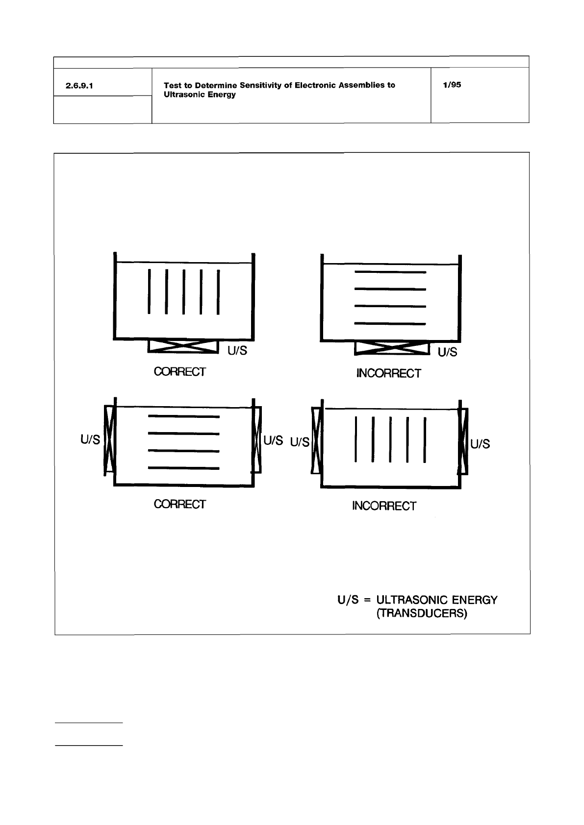
Figure 1
IPC-TM-650
Number
Subject Date
Revision
Page 4 of 5
2.6.9.1
Test
to
Determine
Sensitivity
of
Electronic
Assemblies
to
Ultrasonic
Energy
1/95
INCORRECT
CORRECT
INCORRECT
U/S
=
ULTRASONIC
ENERGY
(TRANSDUCERS)