IPC-TM-650 EN 2022 试验方法--.pdf - 第786页
IPC-TM-650 Page 3 of 3 Number 3.5 Subject Humidity, Connectors Date 7/75 Revision A variations shown in Figure 1 for a period of time correspond¬ ing to one of the test conditions shown in Table 1 . Unless otherwise spec…
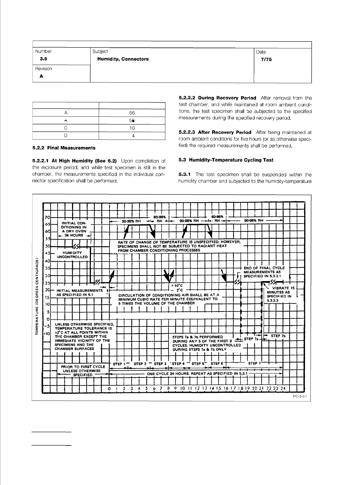
Table I Test Duration
Condition Length of Test (Days)
Figure 1 Graphical Representation of Moisture-Resistance Test
IPC-TM-650
Page 2 of 3
IPC-3-5-1
.
80-98%
70
65
60
55
50
45
40
35
25
10
5
0
-5
-10
STEP
7b
STEP
7
ONE
CYCLE
24
HOURS.
REPEAT
AS
SPECIFIED
IN
5.3.1
ED
SPECIF
0
PRIOR
TO
FIRST
CYCLE
UNLESS
OTHERWISE
INITIAL
CON-
.
DITIONING
IN
A
DAY
OVEN
-
一
24
HOURS
7
END
OF
FINAL
CYCLE
MEASUREMENTS
AS
SPECIFIED
IN
5.3.3.1
rate
of
change
of
temperature
is
unspecified;
however,
SPECIMENS
SHALL
NOT
BE
SUBJECTED
TO
RADIANT
HEAT
FROM
CHAMBER
CONDITIONING
PROCESSES
STEPS
7a
&
7b
PERFORMED
DURING
ANY
5
OF
THE
FIRST
9
CYCLES.
HUMIDITY
UNCONTROLLED
DURING
STEPS
7a
&
7b
ONLY
3
HUMIDITY
UNCONTROLLED
UNLESS
OTHERWISE
SPECIFIED,
TEMPERATURE
TOLERANCE
IS
±2°C
AT
ALL
POINTS
WITHIN
THE
CHAMBER
EXCEPT
THE
IMMEDIATE
VICINITY
OF
THE
SPECIMENS
AND
THE
CHAMBER
SURFACES
5
6
7
8
9
iO
11
12
13
14
15
16
I
7
1
8
19
20
21
?2
23
24
1
l
i
一
・
l
।
•
l
I
一八
A
匕
i
VIBRATE
15
_
MINUTES
AS
SPECIFIED
IN
—
532.2
20-
INITIAL
measurements
…
AS
SPECIFIED
IN
5.1
」
+
10℃
-
20c
CIRCULATION
OF
CONDITIONING
AIR
SHALL
BE
AT
A
MINIMUM
CUBIC
RATE
PER
MINUTE
EQUIVALENT
TO
5
TIMES
THE
VOLUME
OF
THE
CHAMBER
A
56
B
21
C
10
D
4
5.2.2
Final
Measurements
5.2.2.
1
At
High
Humidity
(See
6.2)
Upon
completion
of
the
exposure
period,
and
while
test
specimen
is
still
in
the
chamber,
the
measurements
specified
in
the
individual
con¬
nector
specification
shall
be
performed.
5.2.2.2
During
Recovery
Period
After
removal
from
the
test
chamber,
and
while
maintained
at
room
ambient
condi¬
tions,
the
test
specimen
shall
be
subjected
to
the
specified
measurements
during
the
specified
recovery
period.
S.2.2.3
After
Recovery
Period
After
being
maintained
at
room
ambient
conditions
for
five
hours
(or
as
otherwise
speci¬
fied)
the
required
measurements
shall
be
performed.
5.3
Humidity-Temperature
Cycling
Test
5.3.1
The
test
specimen
shall
be
suspended
within
the
humidity
chamber
and
subjected
to
the
humidity-temperature
Number
3.5
Subject
Humidity,
Connectors
Date
7/75
Revision
A
A
56
B
21
C
10
D
4
IPC-TM-650
Page 3 of 3
Number
3.5
Subject
Humidity,
Connectors
Date
7/75
Revision
A
variations
shown
in
Figure
1
for
a
period
of
time
correspond¬
ing
to
one
of
the
test
conditions
shown
in
Table
1
.
Unless
otherwise
specified,
Test
Condition
B
shall
apply.
5.3.2
Sub-Cycle
(See
6.3)
During
any
five
of
the
first
nine
humidity
temperature
cycles,
the
test
specimen
shall
be
sub¬
jected
to
the
following
sub-cycle,
if
specified.
5.3.2.1
Step
7a
Within
one
to
four
hours
after
the
begin¬
ning
of
Step
7,
the
test
specimen
shall
be
exposed
to
a
tem¬
perature
of
-10℃
土
2
℃
for
a
minimum
period
of
three
hours.
5.3.2.2
Step
7b
Within
fifteen
minutes
after
completion
of
Step
7a,
the
test
specimen
shall
be
subjected
to
the
following
vibration
along
any
one
axis.
Motion
—
Simple
Harmonic
(approx.)
Amplitude
—
0.60
inch
DA
Frequency
Range
—
1
0
to
55
Hz
Sweep
Rate
—
1
0
to
55
to
1
0
Hz
in
60
seconds
(approx.)
Test
Duration
—
15
minutes
5.3.3
Final
Measurements
5.3.3.1
At
High
Humidity
(See
6.2)
Upon
completion
of
Step
6
of
the
final
cycle,
the
test
specimen
shall
be
maintained
at
a
temperature
of
25℃
±
2
℃
and
a
relative
humidity
of
90-98%
for
a
period
of
1-1/2
to
3-1/2
hours,
after
which
the
measurements
specified
in
the
individual
connector
specifica¬
tion
shall
be
performed.
5.3.3.2
During
Recovery
Period
After
removal
from
the
test
chamber,
and
while
maintained
at
room
ambient
condi¬
tions,
the
test
specimen
shall
be
subjected
to
the
specified
measurements
during
the
specified
recovery
period.
5.3.3.3
After
Recovery
Period
Upon
completion
of
Step
6
of
the
final
cycle,
or
following
the
specified
measurements
at
high
humidity
and/or
during
a
recovery
period,
the
test
speci¬
men
shall
be
maintained
at
room
ambient
conditions
for
twenty-four
hours
(or
as
otherwise
specified);
the
required
measurements
shall
then
be
performed.
6.0
Notes
6・1
Acceptance
criteria
shall
be
established
in
terms
of
one,
or
any
combination,
of
the
following:
A.
The
minimum
insulation
resistance
during
or
after
the
test.
B.
Dimensional
changes
affecting
the
functionality
of
the
test
specimen.
C.
Corrosion
of
metals.
D.
Structural
damage
or
deterioration.
6.
2
Due
to
the
difficulty
in
making
measurements
under
high
humidity
conditions,
the
individual
connector
specification
shall
specify
the
particular
precautions
to
be
followed
in
mak¬
ing
measurements
under
such
conditions.
WARNING:
CAUTION:
Material in this Test Methods Manual was voluntarily established by Technical Committees of the IPC. This material is advisory only
and its use or adaptation is entirely voluntary. IPC disclaims all liability of any kind as to the use, application, or adaptation of this
material. Users are also wholly responsible for protecting themselves against all claims or liabilities for patent infringement.
Equipment referenced is for the convenience of the user and does not imply endorsement by the IPC.
Page 1 of 1
r
ASSOCIATION
CONNECTING
/
ELECTRONICS
INDUSTRIES
2215
Sanders
Road
Northbrook,
IL
60062-6135
IPC-TM-650
TEST
METHODS
MANUAL
1
.0
Scope
1.1
To
determine
the
resistance
to
current
leakage
offered
by
the
insulation
materials
and
the
various
seals
of
a
connec¬
tor
to
a
DC
potential
tending
to
produce
such
leakage
through
or
on
the
surface
of
these
members.
The
test
is
especially
useful
in
determining
the
extent
to
which
insulating
properties
are
affected
by
deteriorative
influences,
such
as
heat,
mois¬
ture,
contamination,
or
loss
of
volatile
materials.
2
.0
Reference
Documents
2.1
Information
in
this
section
is
intended
to
parallel
the
test
method
described
in
EIA-RS-364ATP-21
.
3
.0
Test
Specimen
3.1
A
plug,
receptacle,
or
mated
connector
as
specified
in
the
individual
connector
specification.
4
.0
Apparatus
4.1
Megohmmeter
4.1.1
Resistance
measurement
accuracy
shall
be
such
that
the
value
being
measured
is
accurate
to
5
percent.
4.1.2
Test
voltage
shall
be
adjustable
to
within
±
2
percent
of
required
value.
5
.0
Procedure
POTENTIALS
USED
DURING
THIS
TEST
MAY
PROVE
HAZARDOUS
TO
PERSONNEL
TAKE
PRECAU¬
TIONS
TO
PROTECT
PERSONNEL
FROM
ACCIDENTAL
EXPOSURE
TO
THESE
TEST
POTENTIALS.
Number
3.6
Subject
Insulation
Resistance,
Connectors
Date
Revision
7/75
A
Originating
Task
Group
N/A
5
J
If,
required
by
the
individual
connector
specification,
the
plug
and/or
receptacle
shall
be
cleaned
prior
to
the
test
to
insure
that
it
is
free
from
excess
dust,
oil,
moisture,
or
other
surface
contaminants;
all
observed
conditions
shall
be
recorded.
5
.2
Samples
that
have
been
subjected
to
environmental
conditions
shall
be
measured
within
1/2
to
3
hours
after
removal
from
the
chamber,
unless
otherwise
specified.
5
.3
The
insulation
resistance
shall
be
measured
between
individual
pairs
of
immediately
adjacent
contacts
and
between
the
shell
and/or
engaging
hardware
(if
they
exist)
and
the
clos¬
est
individual
contact(s).
NOTE:
The
same
contact
locations
for
a
given
connector
shall
be
used
each
time
the
insulation
resistance
test
is
per¬
formed.
5
.4
The
specified
test
potential
(or
500
volts
DC
if
no
poten¬
tial
is
specified)
shall
be
applied
for
a
two-minute
period.
Immediately
after
this
electrification
period,
the
insulation
resistance
shall
be
measured.
If,
during
the
two-minute
period
the
instrument
indicates
that
the
insulation
resistance
meets
the
specified
minimum
and
is
steady
or
increasing,
the
test
may
be
terminated
before
the
end
of
the
electri
力
cation
period.
EXERCISE
CARE
TO
AVOID
A
DIRECT
SHORT
CIRCUIT
OF
THE
TESTING
APPARATUS
SINCE
DAMAGE
TO
THE
INSTRUMENT
MAY
RESULT.
6.0
Notes
6.1
Acceptance
criteria
shall
be
established
as
the
minimum
level
of
insulation
resistance
compatible
with
end-item
usage
of
the
connector.
This
resistance
is
an
inherent
characteristic
of
connector
geometry
(e.g.,
contact
spacing)
and
materials.