IPC-TM-650 EN 2022 试验方法--.pdf - 第590页
IPC-B-25 IPC-B-25A IPC-6012A IPC-9201 ASTM D-257-93 Figure 1 IPC -B-25A T est Board Material in this T est M ethods Manual was voluntarily establis hed by T echni cal Committees of IPC. Thi s mat erial is a dvisory only …
where:
IPC-TM-650
Page 2 of 3
Number
2.5.14
Subject
Resistivity
of
Copper
Foil
Date
8/76
Revision
A
5.1.2
The
cross-sectional
dimensions
of
the
specimen
may
be
determined
by
micrometer
measurements,
and
a
sufficient
number
of
measurements
shall
be
made
to
obtain
the
mean
cross
section
to
within
±
0.10
percent.
5.1.3
In
case
any
dimension
of
the
specimen
is
less
than
0.100
in.
and
cannot
be
measured
to
the
required
accuracy,
the
cross
section
shall
be
determined
from
the
weight,
den¬
sity,
and
length
of
the
specimen.
5.1.4
When
the
density
is
unknown,
it
shall
be
determined
by
weighing
a
specimen
first
in
air
and
then
in
a
liquid
of
known
density
at
the
test
temperature,
which
shall
be
at
room
temperature
to
avoid
errors
due
to
convection
currents.
5.1.5
Calculate
the
density
from
the
following
formula:
WaXd
o
=
Wa-W|
3
=
density
of
the
specimen,
grams
per
cu
cm,
Wa
=
weight
of
the
specimen
in
air,
grams,
W|
=
weight
of
the
specimen
in
the
liquid,
grams,
and
d
二
density
of
the
liquid
at
the
test
temperature,
grams
per
cu
cm.
5.2
Test
5.2.1
When
potential
leads
are
used,
the
distance
between
each
potential
contact
and
the
corresponding
current
contact
shall
be
at
least
equal
to
1-1/2
times
the
cross-sectional
perimeter
of
the
specimen.
5.2.2
The
yoke
resistance
(between
reference
standard
and
test
specimen)
shall
be
appreciably
smaller
than
that
of
either
the
reference
standard
or
the
test
specimen
unless
a
suitable
lead
compensation
method
is
used,
or
it
is
known
that
the
coil
and
lead
ratios
are
sufficiently
balanced
so
that
variation
in
yoke
resistance
will
not
decrease
the
bridge
accuracy
below
stated
requirements.
5.2.3
Make
resistance
measurements
to
an
accuracy
of
±
0.15
percent.
5.2.4
In
all
resistance
measurements,
the
measuring
current
raises
the
temperature
of
the
specimen
above
that
of
the
sur¬
rounding
medium.
Therefore,
care
shall
be
taken
to
keep
the
magnitude
of
the
current
low,
and
the
time
of
its
use
short
enough
so
that
the
change
in
resistance
cannot
be
detected
with
the
galvanometers.
5.2.5
To
eliminate
errors
due
to
contact
potential,
two
read¬
ings,
one
direct
and
one
with
current
reversed,
must
be
taken
in
direct
succession.
5.2.6
Check
tests
are
recommended
whereby
the
specimen
is
turned
end
for
end,
and
the
test
repeated.
5.2.7
Surface
cleaning
of
the
specimen
at
current
and
potential
contact
points
may
be
necessary
to
obtain
good
electrical
contact.
5.3
Evaluation
5.3.1
Reference
Tests
For
reference
tests,
the
report
should
include
the
following:
1
.Identification
of
test
specimen,
2
.Kind
of
material,
3
.Test
temperature,
4
.Test
length
of
specimen,
5
.Method
of
obtaining
cross-sectional
area:
the
average
val¬
ues
of
micrometer
readings,
or,
if
by
weighing
a
record
of
length,
weight,
and
density
determinations
that
may
be
made,
and
calculated
cross-sectional
area.
6
.Weight,
if
used,
7
.Method
of
measuring
resistance,
8
.Value
of
resistance,
9
.
Reference
temperature,
10
.
Calculated
value
of
resistivity
at
the
reference
temperature,
and
1
1
Previous
mechanical
and
thermal
treatments.
(Since
the
resistivity
of
a
material
usually
depends
upon
them,
these
shall
be
stated
whenever
the
information
is
available.
)
5.3.2
Routing
Tests
For
routine
tests,
only
such
of
the
items
in
paragraph
5.3.1
as
apply
to
the
particular
case,
or
are
significant,
shall
be
reported.
IPC-B-25
IPC-B-25A
IPC-6012A
IPC-9201
ASTM D-257-93
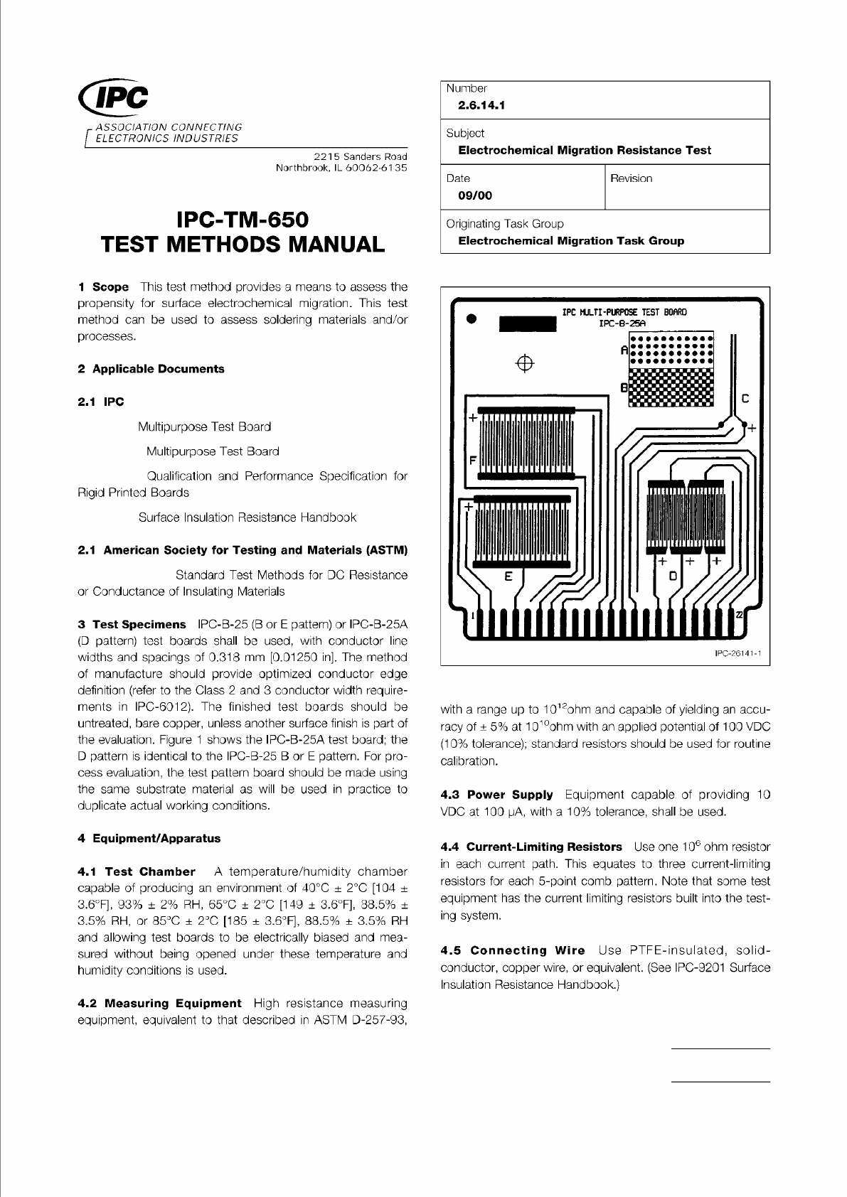
Figure 1 IPC-B-25A Test Board
Material in this Test Methods Manual was voluntarily established by Technical Committees of IPC. This material is advisory only
and its use or adaptation is entirely voluntary. IPC disclaims all liability of any kind as to the use, application, or adaptation of this
material. Users are also wholly responsible for protecting themselves against all claims or liabilities for patent infringement.
Equipment referenced is for the convenience of the user and does not imply endorsement by IPC.
Page 1 of 3
ASSOCIATION
CONNECTING
/
ELECTRONICS
INDUSTRIES
221
5
Sanders
Road
Northbrook,
IL
60062-61
35
IPC-TM-650
TEST
METHODS
MANUAL
1
Scope
This
test
method
provides
a
means
to
assess
the
propensity
for
surface
electrochemical
migration.
This
test
method
can
be
used
to
assess
soldering
materials
and/or
processes.
2
Applicable
Documents
2.1
IRC
Multipurpose
Test
Board
Multipurpose
Test
Board
Qualification
and
Performance
Specification
for
Rigid
Printed
Boards
Surface
Insulation
Resistance
Handbook
2.1
American
Society
for
Testing
and
Materials
(ASTM)
Standard
Test
Methods
for
DC
Resistance
or
Conductance
of
Insulating
Materials
3
Test
Specimens
IPC-B-25
(B
or
E
pattern)
or
IPC-B-25A
(D
pattern)
test
boards
shall
be
used,
with
conductor
line
widths
and
spacings
of
0.318
mm
[0.01250
in].
The
method
of
manufacture
should
provide
optimized
conductor
edge
definition
(refer
to
the
Class
2
and
3
conductor
width
require¬
ments
in
IPC-601
2).
The
finished
test
boards
should
be
untreated,
bare
copper,
unless
another
surface
finish
is
part
of
the
evaluation.
Figure
1
shows
the
IPC-B-25A
test
board;
the
D
pattern
is
identical
to
the
IPG-B-25
B
or
E
pattern.
For
pro¬
cess
evaluation,
the
test
pattern
board
should
be
made
using
the
same
substrate
material
as
will
be
used
in
practice
to
duplicate
actual
working
conditions.
4
Equipment/Apparatus
4.1
Test
Chamber
A
temperature/humidity
chamber
capable
of
producing
an
environment
of
40℃
±
2
℃
[104
±
36F],
93%
土
2%
RH,
65℃
±
2
℃
[149
±
3.6°F],
88.5%
±
3.5%
RH,
or
85℃
+
2
℃
[185
土
3.6°F],
88.5%
土
3.5%
RH
and
allowing
test
boards
to
be
electrically
biased
and
mea¬
sured
without
being
opened
under
these
temperature
and
humidity
conditions
is
used.
Number
2.6.14.1
Subject
Electrochemical
Migration
Resistance
Test
Date
Revision
09/00
Originating
Task
Group
Electrochemical
Migration
Task
Group
IPG-261
41-1
with
a
range
up
to
1012ohm
and
capable
of
yielding
an
accu¬
racy
of
+
5%
at
101°ohm
with
an
applied
potential
of
100
VDC
(10%
tolerance);
standard
resistors
should
be
used
for
routine
calibration.
4.3
Power
Supply
Equipment
capable
of
providing
10
VDC
at
100
pA,
with
a
10%
tolerance,
shall
be
used.
4.4
Current-Limiting
Resistors
Use
one
1
03
6
ohm
resistor
in
each
current
path.
This
equates
to
three
current-limiting
resistors
for
each
5-point
comb
pattern.
Note
that
some
test
equipment
has
the
current
limiting
resistors
built
into
the
test¬
ing
system.
4.5
Connecting
Wire
Use
PTFE-insulated,
solid¬
conductor,
copper
wire,
or
equivalent.
(See
IPC-9201
Surface
Insulation
Resistance
Handbook.)
4.2
Measuring
Equipment
High
resistance
measuring
equipment,
equivalent
to
that
described
in
ASTM
D-257-93,
The Institute for Interconnecting and Packaging Electronic Circuits
2215 Sanders Road • Northbrook, IL 60062
Material in this Test Methods Manual was voluntarily established by Technical Committees of the IPC. This material is advisory only
and its use or adaptation is entirely voluntary. IPC disclaims all liability of any kind as to the use, application, or adaptation of this
material. Users are also wholly responsible for protecting themselves against all claims or liabilities for patent infringement.
Equipment referenced is for the convenience of the user and does not imply endorsement by the IPC.
Page 1 of 5
IPC-TM-650
TEST
METHODS
MANUAL
1
Scope
It
is
the
intent
of
these
guidelines
to
describe
the
material
properties
and
test
procedures
required
to
ensure
effective
RFI
and
EMI
shielding
of
flat
cable.
1.2
Definitions
1.2.1
Relative
Shielding
Effectiveness
The
attenuation
difference
in
the
electromagnetic
field
strength
between
an
unprotected
cable
and
a
shielded
cable
system,
which
is
expressed,
S
=
Rx
+
A
+
B,
where:
Rx
二
the
losses
caused
by
reflection
in
db
A
=
the
losses
caused
by
absorption
in
db
B
二
the
secondary
reflection
losses
of
the
shields
in
db.
The
reflection
losses
are
a
function
of
the
material,
frequency,
and
type
of
field.
Generally,
the
field
within
one
wave
length
from
a
generating
source
will
either
be
predominantly
electric
or
magnetic,
and
at
greater
distance
will
propagate
as
a
plane
wave
made
up
equally
of
electric
and
magnetic
components.
Thus,
the
reflection
losses
for
each
of
these
fields
may
be
designated
by:
Re
=
electric
or
“E”
field
Rh
二
magnetic
or
''H''
field
Rp
=
plane
wave
field
The
absorption
losses
are
a
function
of
the
material
and
fre¬
quency
but
are
independent
of
field
type.
If
these
losses
(A)
are
greater
than
10
db,
the
secondary
reflection
losses
are
negligible,
and
the
expression
for
shielding
effectiveness
reduces
to
S
=
R
+
A.
The
following
are
standard
equations
that
may
be
used
to
obtain
a
rough
approximation
of
a
shield's
effectiveness.
Absorption
Losses:
A
=
3.38
X
10-3t
(uGf)i/2
Reflection
losses:
1
.
Plane
wave
Rp
=
108.2
+
10
log
2.
Magnetic
fields
RH
=
20
log
(蒋)
正
+0.136
r
(梨)
於
+
0.354
(r
<X)
Number
2.5.15
Subject
Guidelines
and
Test
Methods
for
RFI-EMI
Shielding
of
Flat
Cable
Date
Revision
10/86
A
Originating
Task
Group
N/A
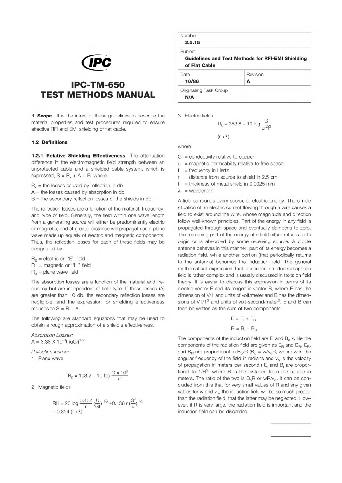
3.
Electric
fields
Re
=
353.6
+
10
log
鸟
urr
(r
4)
where:
G
=
conductivity
relative
to
copper
u
=
magnetic
permeability
relative
to
free
space
f
=
frequency
in
Hertz
r
=
distance
from
source
to
shield
in
2.5
cm
t
二
thickness
of
metal
shield
in
0.0025
mm
九
=
wavelength
A
field
surrounds
every
source
of
electric
energy.
The
simple
situation
of
an
electric
current
flowing
through
a
wire
causes
a
field
to
exist
around
the
wire,
whose
magnitude
and
direction
follow
well-known
principles.
Part
of
the
energy
in
any
field
is
propagated
through
space
and
eventually
dampens
to
zero.
The
remaining
part
of
the
energy
of
a
field
either
returns
to
its
origin
or
is
absorbed
by
some
receiving
source.
A
dipole
antenna
behaves
in
this
manner;
part
of
its
energy
becomes
a
radiation
field,
while
another
portion
(that
periodically
returns
to
the
antenna)
becomes
the
induction
field.
The
general
mathematical
expression
that
describes
an
electromagnetic
field
is
rather
complex
and
is
usually
discussed
in
texts
on
field
theory.
It
is
easier
to
discuss
this
expression
in
terms
of
its
electric
vector
E
and
its
magnetic
vector
B,
where
E
has
the
dimension
of
V/1
and
units
of
volt/meter
and
B
has
the
dimen¬
sions
of
W12
and
units
of
volt-second/meter2
.
E
and
B
can
then
be
written
as
the
sum
of
two
components:
E
=
Ej
+
Er
B
=
Bj
+
Br
The
components
of
the
induction
field
are
E,
and
B,,
while
the
components
of
the
radiation
field
are
given
as
ER
and
BR,
ER,
and
Br
are
proportional
to
Bo/R
(Bo
=
w/voR,
where
w
is
the
angular
frequency
of
the
field
in
radians
and
vo
is
the
velocity
of
propagation
in
meters
per
second.)
E
)
and
B
)
are
propor¬
tional
to
1/R2,
where
R
is
the
distance
from
the
source
in
meters.
The
ratio
of
the
two
is
BOR
or
wR/vo.
It
can
be
con¬
cluded
from
this
that
for
very
small
values
of
R
and
any
given
values
for
w
and
vo,
the
induction
field
will
be
so
much
greater
than
the
radiation
field,
that
the
latter
may
be
neglected.
How¬
ever,
if
R
is
very
large,
the
radiation
field
is
important
and
the
induction
field
can
be
discarded.