IPC-TM-650 EN 2022 试验方法--.pdf - 第299页
IP C- T -5 0 IPC-TM-650 Figure 1 Box BOW 2 1 With constraining for ce applied to both corners of the same edge. 1 & 2 deflection from surface plane. Figure 2 T wist B A x x x x C P oints A, B, C T ouching Base With c…

Where:
D1 = Hole diameter
D2 = Land diameter
L = Load (force)
The formula given utilizes the diameter of both the land
and the hole in the determination of the area of the land,
rather than the radius of each. Thus, a factor of four is applied
to the numerator as the area of a circle as defined by using
the diameter is (π * (diameter)
2
) / 4.
5.4 Evaluation
Examine test specimen for loosening of
bond and for loosening of the land from the base material. It
shall be considered a failure when a land around an unsup-
ported hole is loosened.
6 Notes
6.1
Breaking of a wire, or wire pull-out, shall not be consid-
ered a failure, but the wire shall be resoldered and pulled
again.
6.2
The following details are to be specified in the applicable
performance specification:
a. Test specimen, if other than specified in 3.
b. Force, if other than specified in 5.3.3.
Number
2.4.21
Subject
Land Bond Strength, Unsupported Component Hole
Date
01/07
Revision
F
IPC-TM-650
Note:
Page
2
of
2
IPC-T-50
IPC-TM-650
Figure 1 Box
BOW
2
1
With constraining force applied
to both corners of the same edge.
1 & 2 deflection from surface plane.
Figure 2 Twist
B
A
x
x
x
x
C
Points A, B, C
Touching Base
With constraining force
applied to one corner only.
Material in this Test Methods Manual was voluntarily established by Technical Committees of the IPC. This material is advisory only
and its use or adaptation is entirely voluntary. IPC disclaims all liability of any kind as to the use, application, or adaptation of this
material. Users are also wholly responsible for protecting themselves against all claims or liabilities for patent infringement.
Equipment referenced is for the convenience of the user and does not imply endorsement by the IPC.
Page 1 of 5
r
ASSOCIATION
CONNECTING
/
ELECTRONICS
INDUSTRIES
221
5
Sanders
Road
Northbrook,
IL
60062-6135
IPC-TM-650
TEST
METHODS
MANUAL
1
Scope
This
test
method
covers
three
procedures
used
to
determine
the
bow
and
twist
percentage
of
individual
rigid
printed
boards,
rigid
portions
of
rigid-flex
printed
boards,
and/or
multiple
printed
panels.
Measurements
on
non-
rectangular
samples
pose
a
unique
testing
problem
and
may
necessitate
careful
evaluation
of
the
requirements
imposed
by
the
users
of
this
test
method.
This
test
method
does
not
describe
the
special
considerations
necessary
when
testing
the
bow
and
twist
of
printed
board
assemblies
(i.e.,
compo¬
nent
placement
&
weight,
edge
supports
&
connectors,
etc.).
The
first
two
procedures
describe
production
(Go/No-Go)
methods
that
generally
characterize
the
bow
and
twist
as
being
no
more
than
a
specific
value.
The
other
procedure
is
a
referee
method
used
to
precisely
determine
the
twist.
1.1
Definitions
Bow
and
twist
are
defined
in
IPC-T-50.
The
definitions
are
repeated
in
this
test
method
for
conve¬
nience.
1.1.1
Bow
(Sheet,
Panel,
or
Printed
Board)
The
devia¬
tion
from
flatness
of
a
board
characterized
by
a
roughly
cylin¬
drical
or
spherical
curvature
such
that,
if
the
product
is
rect¬
angular,
its
four
corners
are
in
the
same
plane
(see
Figure
1).
I
PC-2422-1
Number
2.4.22
Subject
Bow
and
Twist
(Percentage)
Date
Revision
6/99
C
Originating
Task
Group
Rigid
Printed
Board
Test
Methods
Task
Group
(7-1
1d)
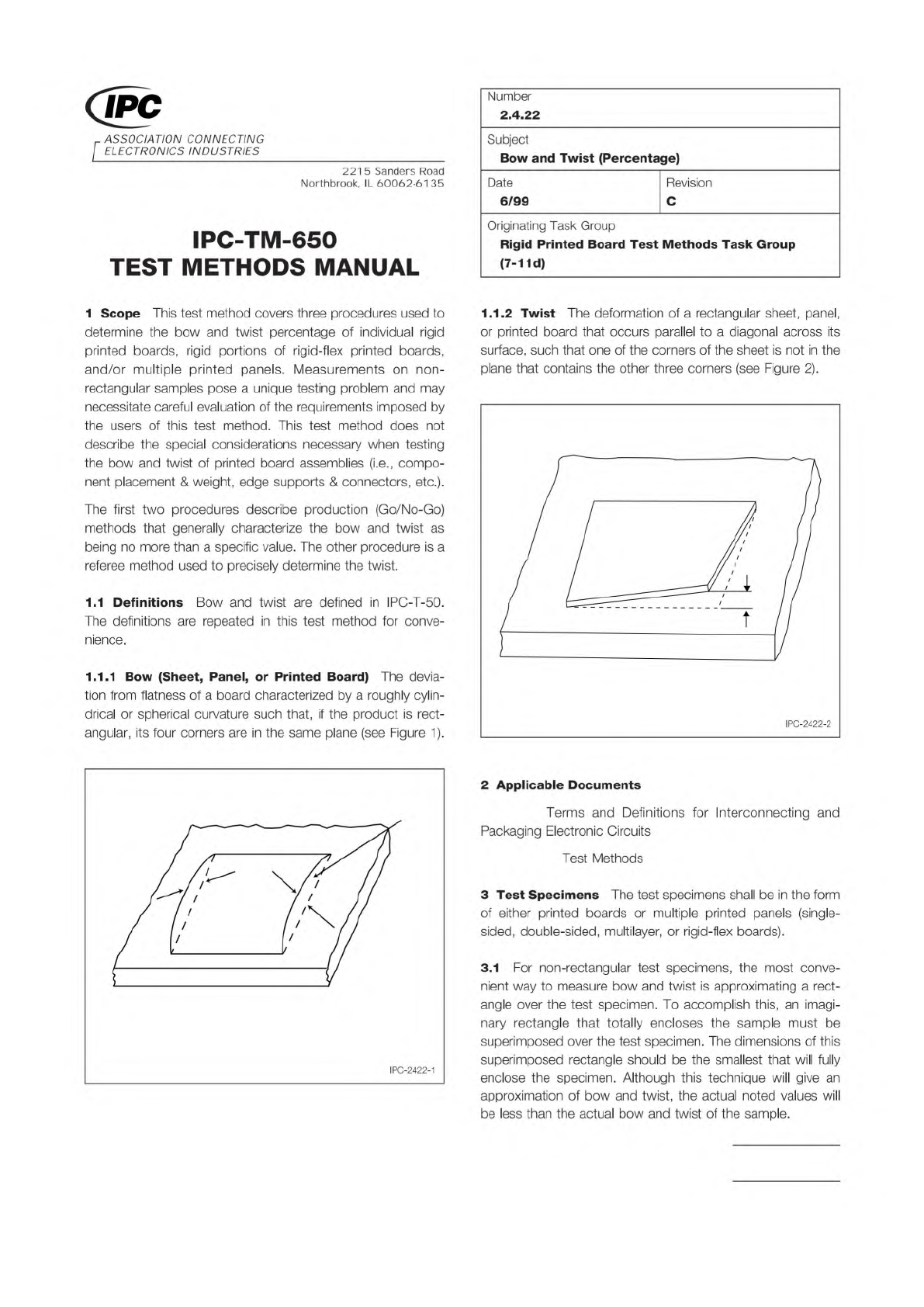
1.1.2
Twist
The
deformation
of
a
rectangular
sheet,
panel,
or
printed
board
that
occurs
parallel
to
a
diagonal
across
its
surface,
such
that
one
of
the
corners
of
the
sheet
is
not
in
the
plane
that
contains
the
other
three
corners
(see
Figure
2).
I
PC-2422-2
2
Applicable
Documents
Terms
and
Definitions
for
Interconnecting
and
Packaging
Electronic
Circuits
Test
Methods
3
Test
Specimens
The
test
specimens
shall
be
in
the
form
of
either
printed
boards
or
multiple
printed
panels
(single¬
sided,
double-sided,
multilayer,
or
rigid-flex
boards).
3.1
For
non-rectangular
test
specimens,
the
most
conve¬
nient
way
to
measure
bow
and
twist
is
approximating
a
rect¬
angle
over
the
test
specimen.
To
accomplish
this,
an
imagi¬
nary
rectangle
that
totally
encloses
the
sample
must
be
superimposed
over
the
test
specimen.
The
dimensions
of
this
superimposed
rectangle
should
be
the
smallest
that
will
fully
enclose
the
specimen.
Although
this
technique
will
give
an
approximation
of
bow
and
twist,
the
actual
noted
values
will
be
less
than
the
actual
bow
and
twist
of
the
sample.
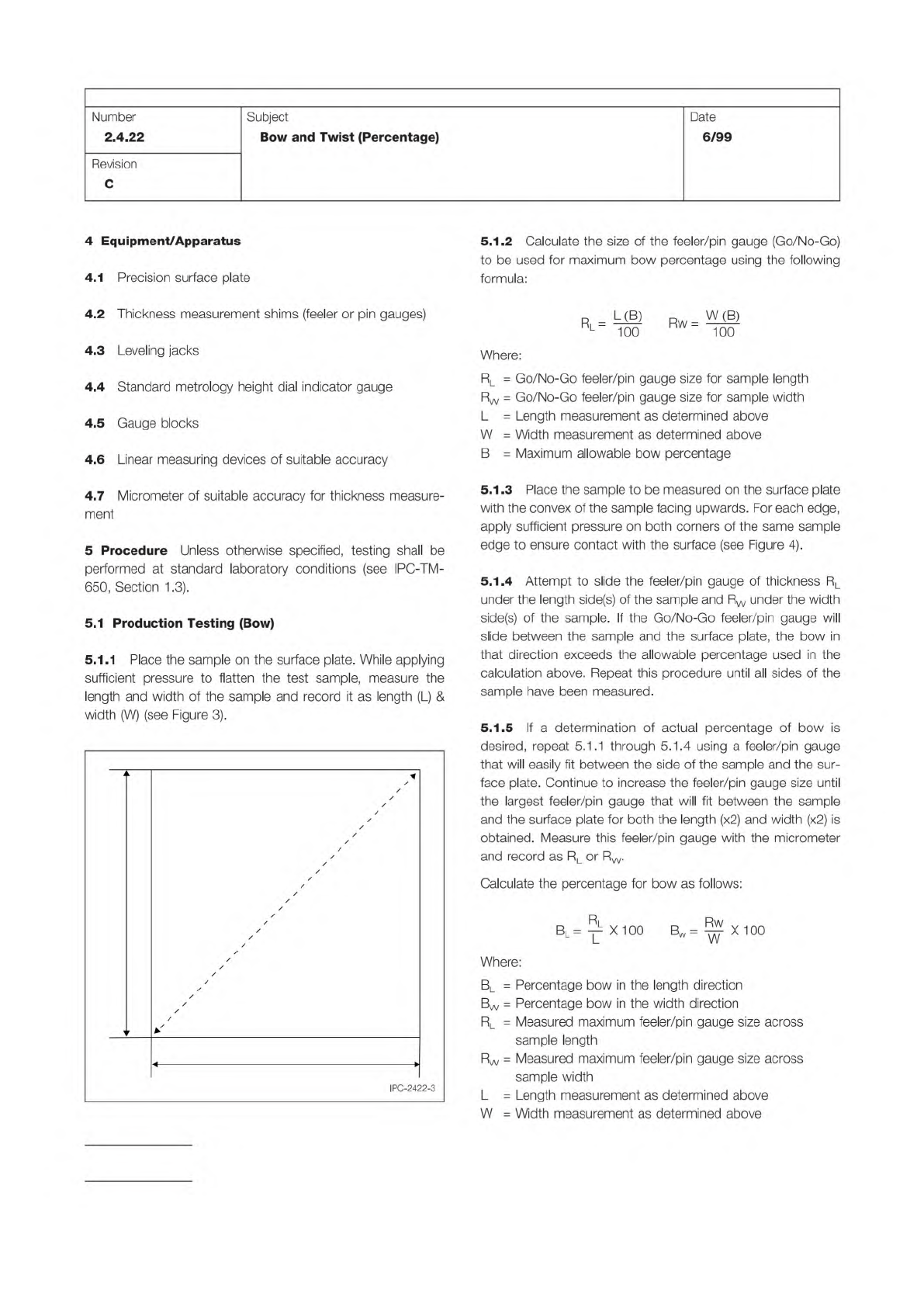
Figure 3 External Measurements
L
D
W
IPC-TM-650
Page 2 of 5
Number
2.4.22
Subject
Bow
and
Twist
(Percentage)
Date
6/99
Revision
C
4
Equipment/Apparatus
4.1
Precision
surface
plate
4.2
Thickness
measurement
shims
(feeler
or
pin
gauges)
4.3
Leveling
jacks
4.4
Standard
metrology
height
dial
indicator
gauge
4.5
Gauge
blocks
4.6
Linear
measuring
devices
of
suitable
accuracy
4.7
Micrometer
of
suitable
accuracy
for
thickness
measure¬
ment
5
Procedure
Unless
otherwise
specified,
testing
shall
be
performed
at
standard
laboratory
conditions
(see
IPC-TM-
650,
Section
1.3).
5.1
Production
Testing
(Bow)
5.1.1
Place
the
sample
on
the
surface
plate.
While
applying
sufficient
pressure
to
flatten
the
test
sample,
measure
the
length
and
width
of
the
sample
and
record
it
as
length
(L)
&
width
(W)
(see
Figure
3).
z
/
/
z
/
/
z
/
/
/
z
/
z
/
/
/
/
/
/
/
/
/
/
/
/
/
/
/
/
/
/
/
/
/
23
Q
L
IPC-242
5.1.2
Calculate
the
size
of
the
feeler/pin
gauge
(Go/No-Go)
to
be
used
for
maximum
bow
percentage
using
the
following
formula:
Rl
=
L(B)
100
Rw
=
W(B)
100
Where:
RL
二
Go/No-Go
feeler/pin
gauge
size
for
sample
length
Rw
二
Go/No-Go
feeler/pin
gauge
size
for
sample
width
L
=
Length
measurement
as
determined
above
W
二
Width
measurement
as
determined
above
B
=
Maximum
allowable
bow
percentage
5.1
.3
Place
the
sample
to
be
measured
on
the
surface
plate
with
the
convex
of
the
sample
facing
upwards.
For
each
edge,
apply
sufficient
pressure
on
both
corners
of
the
same
sample
edge
to
ensure
contact
with
the
surface
(see
Figure
4).
5.1.4
Attempt
to
slide
the
feeler/pin
gauge
of
thickness
RL
under
the
length
side(s)
of
the
sample
and
Rw
under
the
width
side(s)
of
the
sample.
If
the
Go/No-Go
feeler/pin
gauge
will
slide
between
the
sample
and
the
surface
plate,
the
bow
in
that
direction
exceeds
the
allowable
percentage
used
in
the
calculation
above.
Repeat
this
procedure
until
all
sides
of
the
sample
have
been
measured.
5.1.5
If
a
determination
of
actual
percentage
of
bow
is
desired,
repeat
5.1
.1
through
5.1.4
using
a
feeler/pin
gauge
that
will
easily
fit
between
the
side
of
the
sample
and
the
sur¬
face
plate.
Continue
to
increase
the
feeler/pin
gauge
size
until
the
largest
feeler/pin
gauge
that
will
fit
between
the
sample
and
the
surface
plate
for
both
the
length
(x2)
and
width
(x2)
is
obtained.
Measure
this
feeler/pin
gauge
with
the
micrometer
and
record
as
RL
or
Rw.
Calculate
the
percentage
for
bow
as
follows:
Rl
Bl=
j
X100
Bw=
X100
Where:
BL
二
Percentage
bow
in
the
length
direction
Bw
二
Percentage
bow
in
the
width
direction
Rl
=
Measured
maximum
feeler/pin
gauge
size
across
sample
length
Rw
=
Measured
maximum
feeler/pin
gauge
size
across
sample
width
L
=
Length
measurement
as
determined
above
W
二
Width
measurement
as
determined
above