IPC-TM-650 EN 2022 试验方法--.pdf - 第547页
5.4.1 Measure the l ength L of each o f the two split-cylinder resonator sec tions over several locations and compute the mean length of both sect ions. 5.4.2 With the split-cylinder empty (n o substrate) and closed (d=0…
4 Measurement Apparatus
4.1 Split-Cylinder Resonator
The method employs a
split-cylinder resonator, which is a cylindrical cavity separated
into two halves of equal length, with a dielectric substrate
placed in the gap between the two cavity sections. The split-
cylinder resonator must be constructed to allow an adjustable,
variable gap between the two cavity sections for introduction
of the dielectric substrate. Additional details about the con-
struction of a split-post resonator are given in the references
described in 6.2. Over the years there have been commercial
manufacturers of this fixture.
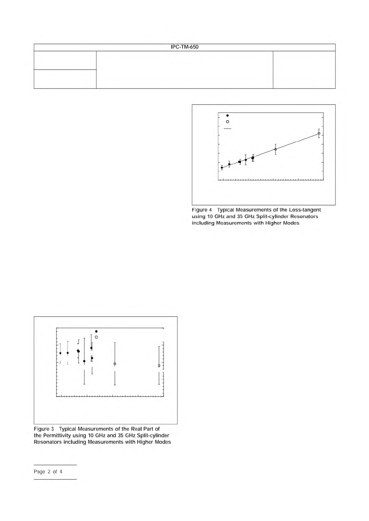
In order to excite and detect the desired fundamental TE
011
resonant mode in the split-cylinder resonator, a coupling loop
is introduced, through a small hole in the cavity wall, in each
of the two cavity regions. The plane of the coupling loop
should be parallel to the plane of the sample, in order to allow
maximum interaction with the vertical component of the mag-
netic field. Each of the coupling loops is connected to a
coaxial transmission line that is connected to the input port of
a network analyzer. To minimize the effect of coupling losses,
the distance to which the loops extend radially into each of the
cavity sections must also be adjustable. In addition to the fun-
damental TE
011
mode, higher modes can be used to extend
the measurement frequency. Typical measurements on fused
silica with higher mode measurements are shown in Figures 3
and 4.
4.2 Network Analyzer
A scalar or vector network analyzer
is necessary to perform the measurement with the split-
cylinder resonator. Commercially available network analyzers
operate over various frequency ranges, so care is needed to
ensure that the network analyzer covers the necessary fre-
quency range for the particular split-cylinder resonator used.
4.3 Digital Micrometer
The dielectric substrate thickness
can be measured with a digital micrometer with a minimal
resolution of 0.001 mm [0.000039 in].
5 Procedure
5.1
Turn on the network analyzer and allow the unit to
warm-up and stabilize according to the manufacturer’s
instructions.
5.2
Connect the network analyzer’s two input ports to the
split-cylinder resonator’s coupling loops using coaxial trans-
mission lines.
5.3
Measure the thickness of the substrate over several
locations using a digital micrometer, and compute the mean
substrate thickness.
5.4
Determine split-cylinder resonator properties. The
length, radius and conductivity of the split-cylinder resonator
must be known before the substrate relative permittivity and
loss tangent can be calculated. If these variables have not
been already determined, the following procedure can be
used:
IPC-25513-3
3.90
10 20
Frequency (GHz)
30 40 50
3.85
3.80
3.75
3.70
Relative Permittivity
10 GHz Split-Cylinder Resonator
35 GHz Split-Cylinder Resonator
TE
011
TE
013
TE
021
TE
023
TE
017
TE
025
TE
011
TE
013
TE
015
IPC-25513-4
7x10
-4
6
5
4
3
2
1
0
10 20
Frequency (GHz)
30 40 50
Loss Tangent
35 GHz Split-Cylinder Resonator
Linear Least Squares Fit
10 GHz Split-Cylinder Resonator
TE
011
TE
013
TE
021
TE
023
TE
017
TE
025
TE
011
TE
013
TE
015
Number
2.5.5.13
Subject
Relative Permittivity and Loss Tangent Using a Split-Cylinder
Resonator
Date
01/07
Revision
IPC-TM-650
Figure
4
Typical
Measurements
of
the
Loss-tangent
using
10
GHz
and
35
GHz
Split-cylinder
Resonators
including
Measurements
with
Higher
Modes
Figure
3
Typical
Measurements
of
the
Real
Part
of
the
Permittivity
using
10
GHz
and
35
GHz
Split-cylinder
Resonators
including
Measurements
with
Higher
Modes
Page
2
of
4
5.4.1
Measure the length L of each of the two split-cylinder
resonator sections over several locations and compute the
mean length of both sections.
5.4.2
With the split-cylinder empty (no substrate) and closed
(d=0), find the TE
011
resonance with the network analyzer.
To reduce the coupling losses to a negligible level, adjust
the radial position of the coupling loops so that the peak of
the resonance curve is less than -40 dB. For the particular
10 GHz split-cylinder resonator described in this method, the
resonant frequency should be approximately 10.04 GHz. If
another split-cylinder geometry is being used, use the follow-
ing approximation to estimate the TE
011
resonant frequency of
an empty split-cylinder resonator:
ƒ
011
=
c
2π
√
(
j
1
a
)
2
+
(
π
2L
)
2
where c is the speed of light in a vacuum, j
1
is the first zero of
the Bessel function of the first kind J
1
, a is the split-cylinder
radius in meters and L is the length, in meters, of each of the
split-cylinder sections as shown in Figure 2.
5.4.3
Once the TE
011
resonance has been identified and
displayed on the network analyzer display, measure the reso-
nant frequency f
011
and quality factor Q of the resonance and
use the following expressions to compute the radius a and the
conductivity σ of the empty split-cylinder’s resonator sections:
a = j
1
[
(
2πƒ
011
c
)
2
−
(
π
2L
)
2
]
−
1
2
σ =
2πƒ
011
µ
0
2R
s
2
where µ
0
is the permeability of free space and
√
µ
0
ε
0
[
(
j
1
a
)
2
+
(
π
2L
)
2
]
3
2
R
s
=
2Q
[
1
2L
(
π
2L
)
2
+
1
a
(
j
1
a
)
2
]
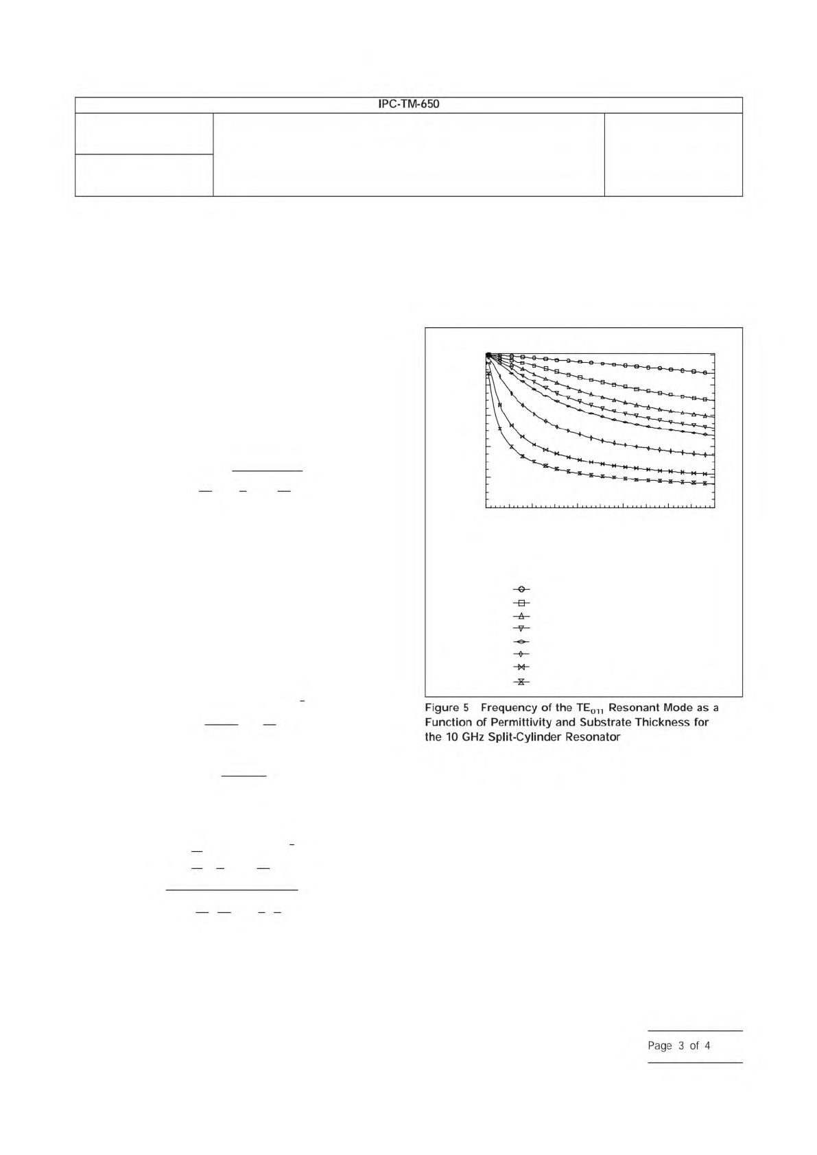
5.5 Estima te the TE
01 1
Resonant Freq uen cy of
Substrate-Loaded Split-Cylinder Resonator
In addition
to the desired TE
011
resonant mode, other modes are excited
in the split-cylinder resonator as shown in Figure 5. Depend-
ing on the thickness and relative permittivity of the dielectric
substrate being measured, the resonant frequency for the
split-cylinder plus substrate can be significantly lower than the
resonant frequency of the empty split-cylinder resonator as
shown in Figure 6.
In order to identify the correct mode, one can use Figure 6 to
predict the resonant frequency of the TE
011
resonant mode.
For a more accurate estimate of this resonant frequency and
the frequencies of the higher-order resonant modes, software
is available from the National Institute of Standards and Tech-
nology (NIST) which calculates the split-cylinder resonator
dimensions, substrate thickness, and provides an estimate of
the relative permittivity of the substrate. As of the publication
of this method, additional commercial vendors are developing
similar software and will be listed through the IPC-TM-650
Test Methods web page.
5.6 Measure the Relative Permittivity and Loss Tangent
5.6.1
Place the substrate in the gap separating the two cav-
ity sections of the split-cylinder resonator in such a way that
IPC-25513-5
Substrate Thickness (mm)
Sample Relative Permittivity
2
4
6
8
10
20
50
100
10
8
6
4
2
0
0 1 2 3 4
5
TE
011
Resonant Frequency (GHz)
Number
2.5.5.13
Subject
Relative Permittivity and Loss Tangent Using a Split-Cylinder
Resonator
Date
01/07
Revision
IPC-TM-650
Figure
5
Frequency
of
the
TE011
Resonant
Mode
as
a
Function
of
Permittivity
and
Substrate
Thickness
for
the
10
GHz
Split-Cylinder
Resonator
Page
3
of
4

1 Scope
The fungus resistance test is used to determine
the resistance of materials to fungi and to determine if such
material is adversely affected by fungi under conditions favor-
able for their development, namely high humidity, warm atmo-
sphere, and presence of inorganic salts.
2 Applicable Documents
None
3 Test Specimen
Specimens must be a minimum size of
50 mm x 50 mm [1.97 in x 1.97 in] with copper foil (if appli-
cable) removed by etching using standard commercial prac-
tices.
4 Apparatus and Reagents
4.1 Test Chamber
The incubator shall be capable of main-
taining 30 ± 1 °C [86 ± 2 °F] and 95 ± 2% relative humidity
and have an ultraviolet (360 nm) source for subsequent
decontamination. Provisions shall be made to prevent con-
densation from dripping on the test item. There shall be free
circulation of air around the test item and the contact area of
fixtures supporting the test item shall be kept to a minimum.
4.2 Sterilizer
4.3 Centrifuge
4.4 pH Meter
4.5 Colony Counter
4.6 Incubator
4.7 Dishwasher
4.8 Petri Dishes
4.9 Filter Paper
4.10 Media Solutions
4.11 Microorganisms
4.12 Atomizer, 15,000 ± 3000 spores
5 Procedures
5.1 Preparation of Test Media
5.1.1 Mineral-Salts Solution
Prepare the solution to contain the following:
Potassium dihydrogen orthophosphate (KH
2
PO
4
) .......... 0.7g
Potassium monohydrogen orthophosphate (K
2
HPO
4
) ... 0.7g
Magnesium sulfate heptahydrate (MgSO
4
c7H
2
O) ........... 0.7g
Ammonium Nitrate (NH
4
NO
3
) ......................................... 1.0g
Sodium chloride (NaCl) .............................................. 0.005g
Ferrous sulfate heptahydrate (FeSO
4
c7H
2
O) ............... 0.002g
Zinc sulfate heptahydrate (ZnSO
4
c7H
2
O) .................... 0.002g
Manganous sulfate monohydrate (MnSO
4
cH
2
O) ......... 0.001g
Distilled water ........................................................... 1000 ml
Sterilize the mineral salt solution by incubating at 121 °C [250
°F] for a minimum of 20 minutes. Adjust the pH of the solution
by the addition of 0.01 normal solution of NaOH so that after
sterilization the pH is between 6.0 and 6.5. Prepare sufficient
salt solutions for the required tests.
5.1.2 Purity of Reagents
Reagent grade chemicals shall
be used in all tests. Unless otherwise specified, it is intended
that all reagents shall conform to the specification of the Com-
mittee on Analytical Reagents of the American Chemical Soci-
ety, where such specifications are available.
5.1.3 Purity of Water
Unless otherwise specified, refer-
ences to water shall be understood to mean distilled water or
water of equal purity.
5.1.4 Preparation of Mixed Spore Suspension
The following test fungi shall be used:
Description .................................................................. ATCC
Aspergillus niger ............................................................ 9642
Chaetomium globosum ................................................. 6205
Gliocladium virens ......................................................... 9645
Aureobasidium pullulans ............................................... 9348
Penicillium funiculosum ................................................. 9644
5.1.5
Maintain cultures of these fungi separately on an
appropriate medium such as potato dextrose agar. However,
the culture of Chaetomium globosum shall be cultured on
3000 Lakeside Drive, Suite 309S
Bannockburn, IL 60015-1249
IPC-TM-650
TEST METHODS MANUAL
Number
2.6.1
Subject
Fungus Resistance of Printed Board Materials
Date
03/07
Revision
G
Originating Task Group
Solder Mask Performance Task Group (5-33b)
ASSOCIATION CONNECTING
ELECTRONICS INDUSTRIES
®
Material
/n
this
Test
Methods
Manual
was
voluntarily
established
by
Technical
Committees
of
I
PC.
This
material
/s
advisory
only
and
"s
use
or
adaptation
,
s
entirely
voluntary.
IPC
disclaims
all
liability
of
any
kind
as
to
the
use,
application,
or
adaptation
of
this
material.
Users
are
also
wholly
responsible
for
protecting
themselves
against
all
claims
or
liabilities
for
patent
infringement.
Equipment
referenced
/s
for
the
convenience
of
the
user
and
does
not
imply
endorsement
by
IPC.
Page
1
of
3