IPC-TM-650 EN 2022 试验方法--.pdf - 第545页
1 Scope This m ethod de scribes the nondestructive mea- surement of the relative permittivity and loss tangent of unclad dielectric substrates at microwave frequencies using a split- cylinder resonator (see Figure 1). Th…
5.5.4 Calculating Average Insertion Loss Slope m
a
and
Intercept b
a
For ‘‘N’’ points between frequency range f1 to
f2 the average insertion loss slope and intercept are defined
as follows in Equations 5-15 to 5-18.
,
avg
=
1
N
Σ
n
,
n
[5-15]
IL
avg
=
1
N
Σ
n
IL(,
n
)
[5-16]
m
A
=
1
N
Σ
n
(,
n
− ,
avg
) ⋅ (IL(,
n
) − IL
avg
)
Σ
(,
n
− ,
avg
)
2
[5-17]
b
A
= IL
avg
− m
A
⋅ ,
avg
[5-18]
Suggested values of f1 and f2 are 1 GHz and 5 GHz respec-
tively.
The slope m
a
is a measure of the total frequency dependent
attenuation, α, which is described in IPC-2141.
Number
2.5.5.12
Subject
Test Methods to Determine the Amount of Signal Loss on
Printed Boards
Date
07/12
Revision
A
IPC-TM-650
Page
24
of
24
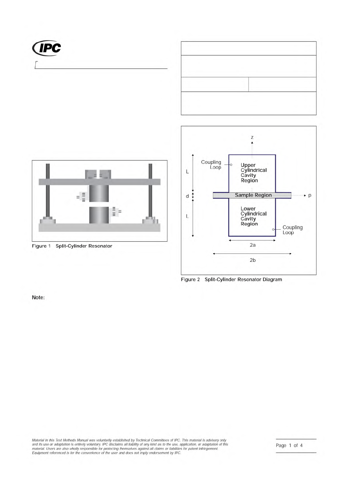
1 Scope
This method describes the nondestructive mea-
surement of the relative permittivity and loss tangent of unclad
dielectric substrates at microwave frequencies using a split-
cylinder resonator (see Figure 1).
This test method is directly applicable for measuring the
in-plane (the plane parallel to the surface of the specimen)
permittivity of the specimen because the electric field is
in-plane. The permittivity of isotropic dielectrics can also be
measured with this method.
This measurement method does not measure the out-
of-plane (direction normal to the surface of the specimen) per-
mittivity of the specimen. However, for most printed boards
the measurement uncertainties associated with this method
are typically less than the difference between in-plane and
out-of-plane permittivity values. Furthermore, comparison with
methods measuring the out-of-plane permittivity is difficult
because those methods typically do not provide measure-
ment confidence intervals.
2 Applicable Documents
See 6.2.
3 Test Specimen
The test specimen is an unclad dielectric
substrate. The substrate geometry can be either square or
circular as long as the substrate extends beyond the diameter
2a of the two cylindrical cavity sections as shown in Figure 2.
In particular, for the 10 GHz split-cylinder resonator discussed
in this method, the dimensions of the substrate should be at
least 50.0 mm [1.97 in] in diameter for circular samples or
50.0 mm [1.97 in] on a side for square samples.
Although the dielectric substrate thickness can vary from
0.05 mm to 5.0 mm [0.0020 in to 0.20 in], thin substrates may
lead to larger measurement uncertainties, while the dielectric
losses in thicker substrates may prevent the split-cylinder fix-
ture from resonating properly. A substrate thickness on the
order of 1.0 mm [0.040 in] is typical.
The measurement theory assumes the dielectric substrate has
a uniform thickness. Therefore, to reduce the measurement
uncertainty, variation and uncertainty in substrate thickness
should be minimized. A typical uncertainty in thickness should
be no more than 0.02 mm [0.00079 in]. In general, warped
samples should also be avoided as these can lead to biases
in the calculated values of the relative permittivity and loss
tangent.
For the split-cylinder resonator described here, the measure-
ment frequency of the split-cylinder resonator is a function of
the relative permittivity and thickness of the substrate. Thicker
substrates and higher values of relative permittivity drive the
resonant frequency lower, as shown in Figure 6.
IPC-25513-1
IPC-25513-2
3000 Lakeside Drive
Bannockburn, IL 60015-1249
IPC-TM-650
TEST METHODS MANUAL
Number
2.5.5.13
Subject
Relative Permittivity and Loss Tangent Using a
Split-Cylinder Resonator
Date
01/07
Revision
Originating Task Group
High Frequency Resonator Test Method Task Group
(D-24c)
ASSOCIATION CONNECTING
ELECTRONICS INDUSTRIES
®
Figure
1
Split-Cylinder
Resonator
z
/
卜
Coupling
L
Loop
—
Q
Upper
Cylindrical
Cavity
Region
d
Sample
Region
A
P
i
卜
L
、
r
Lower
Cylindrical
Cavity
Region
o
_
Coupling
Loop
y
a
2a
2b
Figure
2
Split-Cylinder
Resonator
Diagram
Note:
Material
/n
this
Test
Methods
Manual
was
voluntarily
established
by
Technical
Committees
of
I
PC.
This
material
/s
advisory
only
and
"s
use
or
adaptation
,
s
entirely
voluntary.
IPC
disclaims
all
liability
of
any
kind
as
to
the
use,
application,
or
adaptation
of
this
material.
Users
are
also
wholly
responsible
for
protecting
themselves
against
all
claims
or
liabilities
for
patent
infringement.
Equipment
referenced
/s
for
the
convenience
of
the
user
and
does
not
imply
endorsement
by
IPC.
Page
1
of
4
4 Measurement Apparatus
4.1 Split-Cylinder Resonator
The method employs a
split-cylinder resonator, which is a cylindrical cavity separated
into two halves of equal length, with a dielectric substrate
placed in the gap between the two cavity sections. The split-
cylinder resonator must be constructed to allow an adjustable,
variable gap between the two cavity sections for introduction
of the dielectric substrate. Additional details about the con-
struction of a split-post resonator are given in the references
described in 6.2. Over the years there have been commercial
manufacturers of this fixture.
In order to excite and detect the desired fundamental TE
011
resonant mode in the split-cylinder resonator, a coupling loop
is introduced, through a small hole in the cavity wall, in each
of the two cavity regions. The plane of the coupling loop
should be parallel to the plane of the sample, in order to allow
maximum interaction with the vertical component of the mag-
netic field. Each of the coupling loops is connected to a
coaxial transmission line that is connected to the input port of
a network analyzer. To minimize the effect of coupling losses,
the distance to which the loops extend radially into each of the
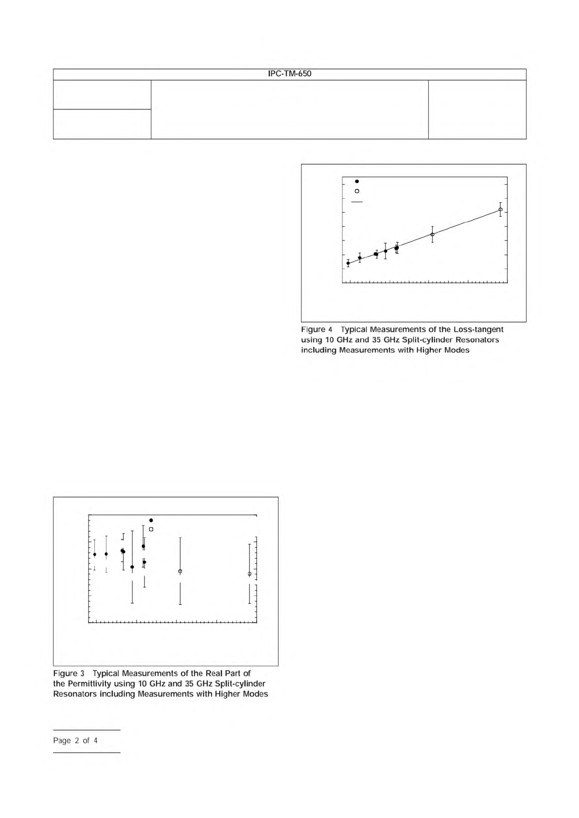
cavity sections must also be adjustable. In addition to the fun-
damental TE
011
mode, higher modes can be used to extend
the measurement frequency. Typical measurements on fused
silica with higher mode measurements are shown in Figures 3
and 4.
4.2 Network Analyzer
A scalar or vector network analyzer
is necessary to perform the measurement with the split-
cylinder resonator. Commercially available network analyzers
operate over various frequency ranges, so care is needed to
ensure that the network analyzer covers the necessary fre-
quency range for the particular split-cylinder resonator used.
4.3 Digital Micrometer
The dielectric substrate thickness
can be measured with a digital micrometer with a minimal
resolution of 0.001 mm [0.000039 in].
5 Procedure
5.1
Turn on the network analyzer and allow the unit to
warm-up and stabilize according to the manufacturer’s
instructions.
5.2
Connect the network analyzer’s two input ports to the
split-cylinder resonator’s coupling loops using coaxial trans-
mission lines.
5.3
Measure the thickness of the substrate over several
locations using a digital micrometer, and compute the mean
substrate thickness.
5.4
Determine split-cylinder resonator properties. The
length, radius and conductivity of the split-cylinder resonator
must be known before the substrate relative permittivity and
loss tangent can be calculated. If these variables have not
been already determined, the following procedure can be
used:
IPC-25513-3
3.90
10 20
Frequency (GHz)
30 40 50
3.85
3.80
3.75
3.70
Relative Permittivity
10 GHz Split-Cylinder Resonator
35 GHz Split-Cylinder Resonator
TE
011
TE
013
TE
021
TE
023
TE
017
TE
025
TE
011
TE
013
TE
015
IPC-25513-4
7x10
-4
6
5
4
3
2
1
0
10 20
Frequency (GHz)
30 40 50
Loss Tangent
35 GHz Split-Cylinder Resonator
Linear Least Squares Fit
10 GHz Split-Cylinder Resonator
TE
011
TE
013
TE
021
TE
023
TE
017
TE
025
TE
011
TE
013
TE
015
Number
2.5.5.13
Subject
Relative Permittivity and Loss Tangent Using a Split-Cylinder
Resonator
Date
01/07
Revision
IPC-TM-650
Figure
4
Typical
Measurements
of
the
Loss-tangent
using
10
GHz
and
35
GHz
Split-cylinder
Resonators
including
Measurements
with
Higher
Modes
Figure
3
Typical
Measurements
of
the
Real
Part
of
the
Permittivity
using
10
GHz
and
35
GHz
Split-cylinder
Resonators
including
Measurements
with
Higher
Modes
Page
2
of
4