IPC-TM-650 EN 2022 试验方法--.pdf - 第689页
T a ble 1 Step T e st C ondition A T est Condition B T est Condition C T emperature Time T emperature Time T emperature Time 1 2 3 4 0, +0/- 5 25, +10/-5 +70, +5/-0 25, +10/-5 15 0 15 0 -40, +0/-5 25, +10/-5 +85, +5/-0 2…
IPC-D-275
NOTE:
The Institute for Interconnecting and Packaging Electronic Circuits
2215 Sanders Road • Northbrook, IL 60062-6135
Material in this Test Methods Manual was voluntarily established by Technical Committees of the IPC. This material is advisory only
and its use or adaptation is entirely voluntary. IPC disclaims all liability of any kind as to the use, application, or adaptation of this
material. Users are also wholly responsible for protecting themselves against all claims or liabilities for patent infringement.
Equipment referenced is for the convenience of the user and does not imply endorsement by the IPC.
Page 1 of 2
IPC-TM-650
TEST
METHODS
MANUAL
1
.0
Scope
The
purpose
of
this
method
is
to
determine
the
physical
endurance
of
printed
boards
to
sudden
exposure
to
extreme
changes
in
temperature
and
the
effect
of
alternate
exposures
to
these
extremes.
The
exposure
of
the
printed
board
specimens
to
the
high
and
low
temperature
extremes
is
designed
to
cause
physical
damage,
deterioration,
or
signifi¬
cant
changes
in
resistance.
2
.0
Applicable
Documents
Design
Standard
for
Rigid
Printed
Boards
and
Rigid
Printed
Board
Assemblies.
3
.0
Test
Specimen
Test
coupon
“D”
from
IPC-D-275
or
other
suitable
test
coupon
(see
6.1a).
4
.0
Apparatus
4.1
An
automatically
controlled
dual
temperature
environ¬
mental
test
chamber
or
other
dual
chamber
apparatus
capable
of
maintaining
-65,-55,-40
or
0
℃
+
0
-5℃
[-85,
-67, -40,
+32°F
+
0
-9°F]
in
the
low
temperature
chamber
and
70,
85,
105,
125,
150
or
170
+5
-0℃
[158,
185,
221,
257,
302
or
338°
F
+9
-0°F]
in
the
high
temperature
chamber.
The
temperature
extremes
(high
and
low)
that
are
required
is
dependent
on
the
base
material
of
the
specimen
that
is
to
be
tested
(see
6.1b
).
The
recovery
capacity
of
the
test
chambers
shall
be
such
that
the
internal
chamber
air
tem¬
perature
shall
reach
the
specified
temperature
within
2
min¬
utes
after
the
specimen(s)
have
been
transferred
to
the
test
chamber.
4.2
An
electrical
resistance
meter
capable
of
accuracies
of
0.5
milliohm
or
better
with
Kelvin
(4
terminal)
type
leads.
A
Kelvin
type
double
bridge
or
potentiometer
of
the
specified
accuracy
may
also
be
used
(see
6.2).
5.1
Preparation
Wire
up
test
specimen
with
Kelvin
-type
leads
at
the
points
where
measurements
will
be
made.
Number
2.6.7
Subject
Thermal
Shock
&
Continuity,
Printed
Board
Date
Revision
8/97
A
Originating
Task
Group
Rigid
Board
T.M.
Task
Group,
7-1
1d
specimen
in
the
approximate
center
of
the
high
temperature
chamber.
First
specimens
shall
be
placed
approximately
13
mm
[0.5
in]
apart
and
aligned
in
a
manner
to
permit
maximum
heat
transfer
to
the
test
specimen(s).
5.2
Test
5.2.1
Thermal
Shock
Cycle
5.2.1.
1
The
specimens
shall
be
subjected
to
100
tempera¬
ture
cycles
in
accordance
with
the
applicable
test
condition
of
Table
1.
5.2.1.
2
Transfer
time
between
chambers
shall
be
less
than
2
minutes.
The
thermal
capacity
of
the
test
chamber
used
shall
be
such
that
the
ambient
temperature
shall
reach
the
specified
temperature
within
2
minutes
after
the
specimen
has
been
transferred
to
the
appropriate
chamber.
5.2.1.
3
Interconnection
resistance
measurements
shall
be
taken
before
the
test,
during
the
first
cycle
at
high
tempera¬
ture,
and
during
the
last
cycle
at
high
temperature.
In-cham-
ber
resistance
measurements
should
be
taken
during
the
last
few
minutes
of
chamber
exposure.
Care
should
also
be
taken
to
measure
samples
after
approximately
the
same
duration
at
chamber
temperature.
5.3
Evaluation
The
maximum
change
in
resistance
between
the
first
and
100th
cycle
shall
be
evaluated
for
acceptability
to
the
requirements
of
the
applicable
specifica¬
tion.
6.0
Notes
6.1
The
following
details
are
to
be
specified
in
the
applicable
performance
specification:
a.
Test
specimen,
if
other
than
specified
in
3.0.
b.
Test
condition,
if
other
than
specified
in
4.1
.
c.
Maximum
change
in
resistance.
5.1.1
Operate
chamber
(or
chambers)
and
allow
to
stabilize
at
the
high
and
low
temperature
required.
Clamp
or
suspend
Table 1
Step
Test Condition A Test Condition B Test Condition C
Temperature Time Temperature Time Temperature Time
1
2
3
4
0, +0/-5
25, +10/-5
+70, +5/-0
25, +10/-5
15
0
15
0
-40, +0/-5
25, +10/-5
+85, +5/-0
25, +10/-5
15
0
15
0
-55, +0/-5
25, +10/-5
+105, +5/-0
25, +10/-5
15
0
15
0
Step
Test Condition D Test Condition E Test Condition F
Temperature Time Temperature Time Temperature Time
1
2
3
4
-55, +0/-5
25, +10/-5
+125, +5/-0
25, +10/-5
15
0
15
0
-65, +0/-5
25, +10/-5
+150, +5/-0
25, +10/-5
15
0
15
0
-65, +0/-5
25, +10/-5
+170, +5/-0
25, +10/-5
15
0
15
0
Tolerance shall be +2 and -0 minutes.
Table 2
Rigid Type NEMA Test Condition
A
GP, GT, GX, GY B
GE C
AF, BF, BI, CF, GF, GB D
GH, GM E
AI, GI, QI F
IPC-TM-650
Number
Subject Date
Revision
Page 2 of 2
2.6.7
Thermal
Shock
&
Continuity,
Printed
Board
8/97
A
6.1.1
Unless
otherwise
specified
by
the
applicable
perfor¬
mance
specification,
the
following
base
material
types/
temperature
ratings
are
recommended.
6.2
Suggested
sources
for
capable
test
equipment:
Cambridge
Technology
Model
51
OA
Micro-Ohmmeter
23
Elm
Street
Watertown,
MA
02172
(617)
923-1181
Hewlett-Packard
Model
4338A
Milliohmmeter
9800
Muirlands
Avenue
Irvine,
CA
92718
(714)
472-3000
Keithly
Instruments
Model
580
Micro-ohmmeter
28775
Aurora
Road
Cleveland,
OH
44139
(800)
552-1115
IPC-CC-830
Class Low Temperature High Temperature
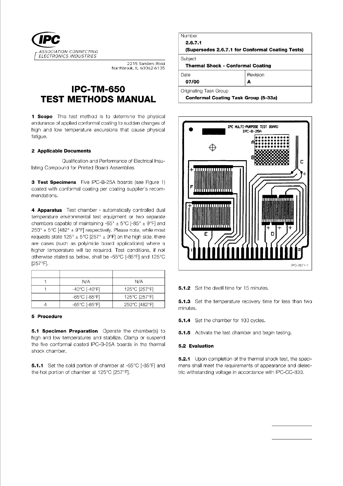
Figure 1 IPC-B-25A Test Board
Material in this Test Methods Manual was voluntarily established by Technical Committees of IPC. This material is advisory only
and its use or adaptation is entirely voluntary. IPC disclaims all liability of any kind as to the use, application, or adaptation of this
material. Users are also wholly responsible for protecting themselves against all claims or liabilities for patent infringement.
Equipment referenced is for the convenience of the user and does not imply endorsement by IPC.
Page 1 of 1
ASSOCIATION
CONNECTING
/
ELECTRONICS
INDUSTRIES
221
5
Sanders
Road
Northbrook,
IL
60062-61
35
IPC-TM-650
TEST
METHODS
MANUAL
1
Scope
This
test
method
is
to
determine
the
physical
endurance
of
applied
conformal
coating
to
sudden
changes
of
high
and
low
temperature
excursions
that
cause
physical
fatigue.
2
Applicable
Documents
Qualification
and
Performance
of
Electrical
Insu¬
lating
Compound
for
Printed
Board
Assemblies
3
Test
Specimens
Five
IPC-B-25A
boards
(see
Figure
1)
coated
with
conformal
coating
per
coating
supplier's
recom¬
mendations.
4
Apparatus
Test
chamber
-
automatically
controlled
dual
temperature
environmental
test
equipment
or
two
separate
chambers
capable
of
maintaining
-65°
±
5
℃
[-85°
±
9°F]
and
250°
土
5
℃
[482°
土
9°F]
respectively.
Please
note,
while
most
requests
state
125°
±
5
℃
[257。
±
9°F]
on
the
high
side,
there
are
cases
(such
as
polyimide
board
applications)
where
a
higher
temperature
will
be
required.
Test
conditions,
if
not
otherwise
stated
as
below,
shall
be
-65℃
[-85°F]
and
125℃
[257°F].
1
N/A N/A
2
-40℃
[-40°F]
125℃
[257°F]
3
-65℃
[-85°F]
125℃
[257°F]
4
-65℃
[-85°F]
250℃
[482°F]
5
Procedure
5.1
Specimen
Preparation
Operate
the
chamber(s)
to
high
and
low
temperatures
and
stabilize.
Clamp
or
suspend
the
five
conformal
coated
IPC-B-25A
boards
in
the
thermal
shock
chamber.
5.1.1
Set
the
cold
portion
of
chamber
at
-65℃
[-85°F]
and
the
hot
portion
of
chamber
at
125℃
[257°F].
Number
2.6.7.1
(Supersedes
2.6.7.
1
for
Conformal
Coating
Tests)
Subject
Thermal
Shock
-
Conformal
Coating
Date
07/00
Revision
A
Originating
Task
Group
Conformal
Coating
Task
Group
(5-33a)
5.1.2
Set
the
dwell
time
for
15
minutes.
5.1.3
Set
the
temperature
recovery
time
for
less
than
two
minutes.
5.1.4
Set
the
chamber
for
100
cycles.
5.1.5
Activate
the
test
chamber
and
begin
testing.
5.2
Evaluation
5.2.1
Upon
completion
of
the
thermal
shock
test,
the
speci¬
mens
shall
meet
the
requirements
of
appearance
and
dielec¬
tric
withstanding
voltage
in
accordance
with
IPC-CC-830.