S 20 Series Maintenance I.pdf - 第473页
2000 年 6 月版 S 2 0 系列维修培训指南 I 9 传送系统 12 顶部和底部位置限位 开关 顶部和底部位置限位 开关 顶部和底部位 置限位 开关 顶部和底部位置限位 开关 用顶部和底部限位开 关 可 调整顶部 和底部 的 终点 位置 限位开关用 2 个销子 触发 并固定在升降 台台板上 注意 检查 PCB 夹紧 和 PCB 支承的 高 度 Abb. 9. 1 .6 升降台台板限位 开关 原理 gr ub s cr ews l…
S 20 系列维修培训指南 I 2000 年 6 月版
9 传送系统
11
9.1.6
9.1.69.1.6
9.1.6 升降台顶部和底部位置调整
升降台顶部和底部位置调整 升降台顶部和底部位置调整
升降台顶部和底部位置调整
Abb. 9.1.5
升降台顶部和底部位置调整
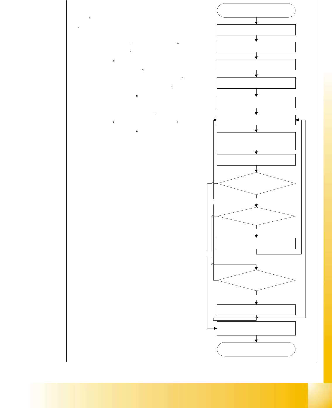
Set the left tripping pin to 25 or 40 mm
stroke position for table bottom
position
Place PCB on the centre conveyor
Place a single PCB support pin
beneath the PCB on the lifting table
At station computer select
"Processing Suspended"
Select "Single functions PCB transport
" menu
Select " Transport functions " menu
Select " Acuate Clamping " to move
the lifting table to the upper position.
Observe the position of the PCB
support pin relative to the underside of
the PCB
Was the gap correct
( approx. 0.1mm ) ?
No
Is the pin position
too low ?
Yes
Move the right tripping pin down
slightly
No
Is the pin position too high?
Move the right tripping pin slightly up
Yes
Exit single functions
Select "Processing On"
Yes
No
Select "Acuate Clamping" to move the
lifting table to the lower position
调整图上显示的限位销位置 , 按照侧面显的
流程图
就可以调整升降台顶部和底部位
置
左限位销决定底部位置 可设定 2 个位置
第一个位置是标准设置 允许升降台从顶部
位置下降 25mm
第二个位置允许升降台从
顶部位置下降更多至 40mm
第二个位置用
于双面 PCB ( 在其底面必须有额外的间隙 )
这一位置的缺点是升降台循环时间稍长 由
此造成的工序时间也较长
右限位销决定升降台的顶部位置 调整这个
位置时必须小心
不要把升降台升得过高
以免与传送导轨下侧相撞
2000 年 6 月版 S 20 系列维修培训指南 I
9 传送系统
12
顶部和底部位置限位开关
顶部和底部位置限位开关顶部和底部位 置限位开关
顶部和底部位置限位开关
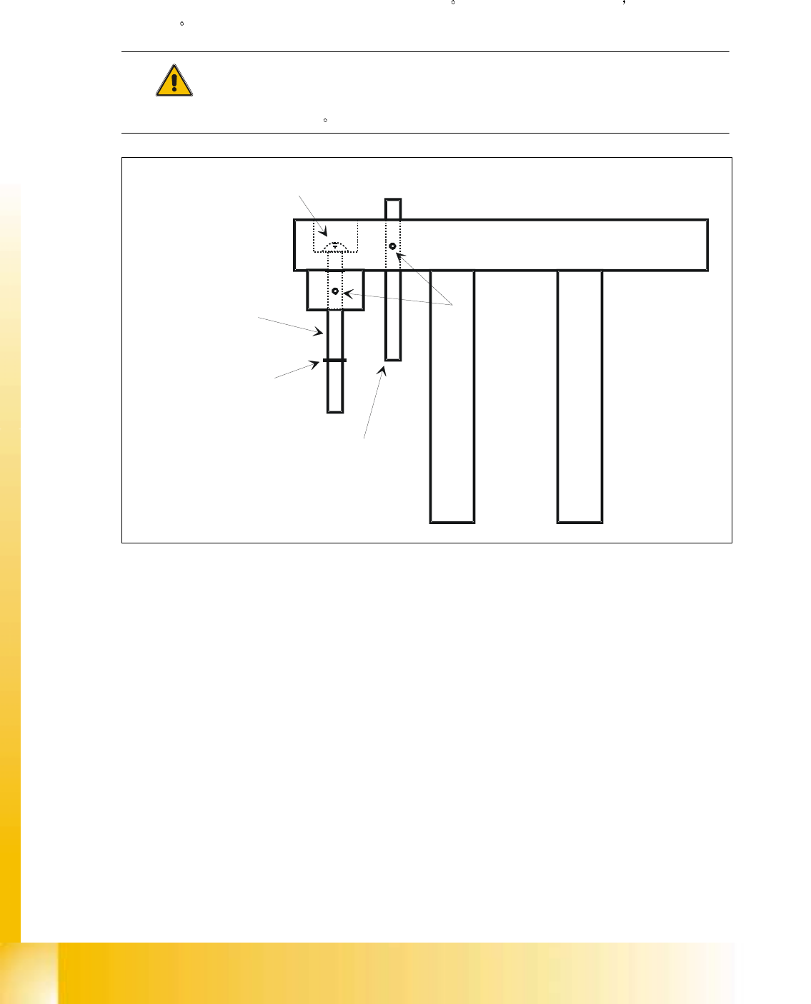
用顶部和底部限位开关可调整顶部 和底部的终点位置
限位开关用 2 个销子触发 并固定在升降
台台板上
注意
检查 PCB 夹紧和 PCB 支承的高度
Abb. 9.1.6 升降台台板限位开关原理
grub screws
lifting table plate
stop 40mm
stroke
tripping pin lifitng table
bottom position
tripping pin lifting table
top position
stop screw
25mm stroke

S 20 系列维修培训指南 I 2000 年 6 月版
9 传送系统
13
9.2 PCB 传送系统的齿轮马达
PCB 传送系统的齿轮马达PCB 传送系统的齿轮马达
PCB 传送系统的齿轮马达
9.2.1
9.2.19.2.1
9.2.1更换输入和中心传送导轨的齿轮马达
更换输入和中心传送导轨的齿轮马达更换输入和中心传送导轨的齿轮马达
更换输入和中心传送导轨的齿轮马达
9.2.1.1
9.2.1.19.2.1.1
9.2.1.1备件
备件备件
备件 辅助材料和设备
辅助材料和设备辅助材料和设备
辅助材料和设备
带同步盘的齿轮马达 编号 00324405-01
SITEST 编号
9.2.1.2 从输入和中心传送导轨上拆除齿轮马达
从输入和中心传送导轨上拆除齿轮马达从输入和中心传送导轨上拆除齿轮马达
从输入和中心传送导轨上拆除齿轮马达
!
印刷电路板传送导轨宽度应设为 最大 以便顺利地进行维修工作
!
将悬臂移送到印刷电路板传送导 轨外
!
在主开关上关掉机器并将其从主 电源上断开
!
进行维修时 机器不能合闸
!
在齿轮马达的安装位置做上标记 并在电缆接头上栓上标签 , 以防重新安装时极性发生错误
!
从马达接头上取下电缆终端套管
!
从传送导轨马达上取下固定连接 电缆用的热可收缩套
!
拧开并卸下齿轮马达 A 的 4 个安装螺钉 4 个 M3 槽头螺钉
!
把齿轮马达稍稍向一面倾斜 同时小心地把齿 轮马达向后拉 B 确保同步盘不卡在齿轮带
内