99312_UR5_User_Manual_zh_E67ON_Global.pdf - 第83页
SF# Safety Func ti o n D e s c ri pti on What i s c ont rol l ed? SF9 Inte rnal J oi nt Speed Li mi t Exc eed in g the mom entu m li mi t res ul ts in a Cat 0 st op5 ( IEC 602 04-1 ). The mom en tum li mit is very use fu…
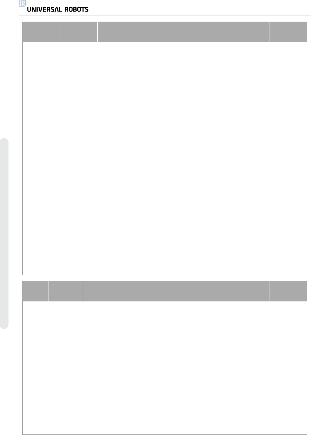
SF#
Safety
Function
Description
What is
controlled?
SF2
Logic and
outputs
INTERNAL
Safeguard
stop
(Protective
Stop)
This safety function is initiated by an external protective
device using safety inputs which will initiate a Cat 2 stop per
IEC 60204-1. For the functional safety rating of the complete
integrated safety function, add the PFHd of the external
protective device to the PFHd of SF2. If a PLd Cat3 stop is
needed for protective devices, connect the protective device
and configure the input as if it were an external Estop input
(See SF0).
Robot Arm
SF3
Internal
Joint
Position
Limit (soft
axis
limiting)
Exceeding the joint position limit results in a Cat 0 stop (IEC
60204-1). Each joint can have its own limit. Directly limits the
set of allowed joint positions that the joints can move to. It is
set directly in the safety setup part of the UI where you can
enter values. It is a means of safety-rated soft axis limiting
and space limiting, according to ISO 10218-1:2011, 5.12.3.
Joint
(each)
SF4
Internal
Joint
Speed
Limit
Exceeding a joint speed limit results in a Cat 0 stop5 per IEC
60204-1. Each joint can have its own limit. Directly limits the
set of allowed joint speeds which the joints are allowed to
perform. It is set directly in the safety setup part of the User
Interface where you can enter values. It can be used to limit
fast joint movements, for instance to limit risks related to
singularities.
Joint
(each)
SF5
Internal
Joint
Torque
Limit
Exceeding the joint torque limit (each joint) results in a Cat 0
stop5 (per IEC 60204-1). This is not accessible to the user
as it is a factory setting, part of the force limiting safety
function.
Joint
(each)
SF#
Safety
Function
Description
What is
controlled?
SF6
Internal
TCP Pose
Limit
Monitors the TCP Pose (position and orientation), any violation of
a safety plane or TCP Pose Limit will result in a Cat 0 stop5 (IEC
60204-1). This safety function consists of two parts. One is the
safety planes for limiting the possible TCP positions. The second
is the TCP orientation limit, which is entered as an allowed
direction and a tolerance. This provides TCP inclusion/ exclusion
zones due to the safety planes. When a limit (plane or TCP pose)
is violated, a Cat 0 stop is initiated.
TCP
SF7
Internal
TCP
Speed
Limit
Exceeding the TCP speed limit results in a Cat 0 stop5 (IEC
60204-1).
TCP
SF8
Internal
TCP
Force
Limit
Exceeding the TCP force limit results in a Cat 0 stop5 (IEC
60204-1). Limits the external clamping force exerted by the robot.
See also Joint Torque Limit (SF5).
TCP
UR5 72 用 户 手 册
版 权所 有 © 2009–2021UniversalRobotsA/S。保留 所 有 权利。
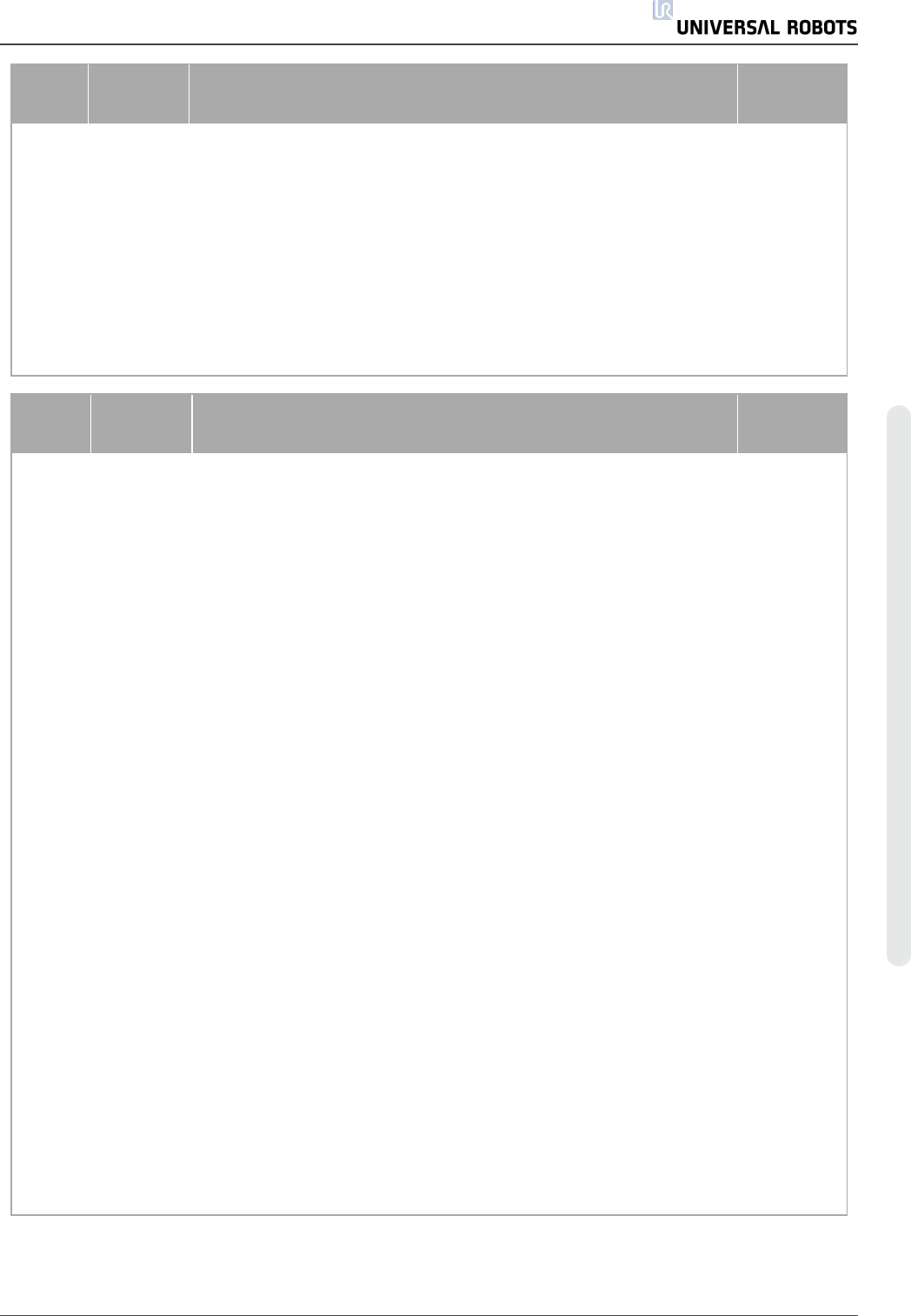
SF#
Safety
Function
Description
What is
controlled?
SF9
Internal
Joint
Speed
Limit
Exceeding the momentum limit results in a Cat 0 stop5 (IEC
60204-1). The momentum limit is very useful for limiting transient
impacts. The Momentum Limit affects the entire robot arm.
Robot Arm
SF10
Internal
Power
Limit
Exceeding the power limit results in a Cat 0 stop5 (IEC 60204-1).
This function monitors the mechanical work (sum of joint torques
times joint angular speeds) performed by the robot, which also
affects the current to the robot arm as well as the speed of the
robot arm. This function dynamically limits the current/torque but
maintain the speed.
Robot Arm
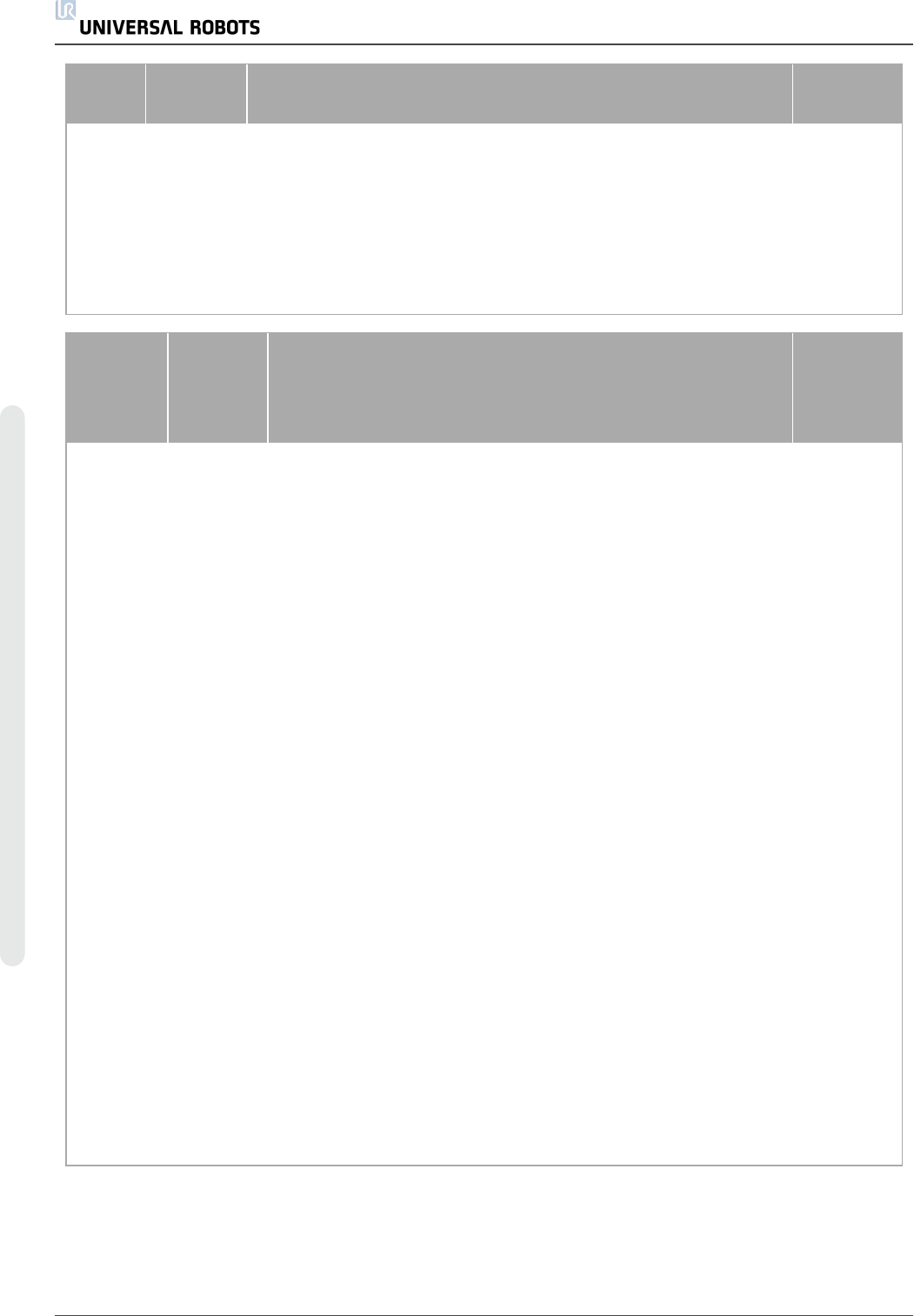
SF#
Safety
Function
Description
What is
controlled?
SF11
Internal
as a
function
with
dual
outputs
UR Robot
Estop
Output
When configured for Estop output and there is an Estop condition
(see SF1), the dual outputs are LOW. If there is no Estop
condition, dual outputs are high. Pulses are not used but they are
tolerated. For the integrated functional safety rating with an
external Estop device, add the PFHd of the UR Estop function
(SF0 or SF1) to the PFHd of the external logic (if any) and its
components (e.g. Estop pushbutton).
External
connection
to logic
and/or
equipment
SF12
Internal
as a
function
with
dual
outputs
UR Robot
Moving:
Digital
Output
Whenever the robot is moving (motion underway), the dual digital
outputs are LOW. Outputs are HIGH when no movement. The
functional safety rating is for what is within the UR robot. The
integrated functional safety performance requires adding this
PFHd to the PFHd of the external logic (if any) and its
components.
External
connection
to logic
and/or
equipment
SF13
Internal
as a
function
with
dual
outputs
UR Robot
Not
stopping:
Digital
Output
Whenever the robot is STOPPING (in process of stopping or in a
stand-still condition) the dual digital outputs are HIGH. When
outputs are LOW, robot is NOT in the process or stopping and
NOT in a stand-still condition. The functional safety rating is for
what is within the UR robot. The integrated functional safety
performance requires adding this PFHd to the PFHd of the
external logic (if any) and its components.
External
connection
to logic
and/or
equipment
SF14
Internal
as a
function
with
dual
outputs
UR Robot
Reduced
Mode:
Digital
Output
Whenever the robot is in reduced mode, the dual digital outputs
are LOW. See Robot Reduced Mode below. The functional
safety rating is for what is within the UR robot. The integrated
functional safety performance requires adding this PFHd to the
PFHd of the external logic (if any) and its components.
External
connection
to logic
and/or
equipment
用 户 手 册 73 UR5
版 权所 有 © 2009–2021UniversalRobotsA/S。保留 所 有 权利。
SF#
Safety
Function
Description
What is
controlled?
SF15
Internal
as a
function
with
dual
outputs
UR Robot
Not
Reduced
Mode:
Digital
Output
Whenever the robot is NOT in reduced mode, the dual digital
outputs are LOW. The functional safety rating is for what is within
the UR robot. The integrated functional safety performance
requires adding this PFHd to the PFHd of the external logic (if
any) and its components.
External
connection
to logic
and/or
equipment
TUV
NORD
Certified
SF
Safety
Function
Description
What is
controlled?
Robot
Reduced
Mode
Internal
Logic and
Outputs,
with Dual
Inputs (1
through 4)
Reduced Mode can be initiated by a safety plane/ boundary
(starts when at 2cm of the plane and reduced mode settings
are achieved within 2cm of the plane) or by use of an input to
initiate (will achieve reduced settings within 500ms). When the
external connections are Low, Reduced Mode is initiated.
Reduced Mode means that ALL reduced mode limits are
ACTIVE Reduced mode is not a safety function, rather it is a
state affecting the settings of the following safety function
limits: SF3 joint position, SF4 joint speed, SF6 TCP pose limit,
SF7 TCP speed, SF8 TCP force, SF9 momentum, and SF10
power.
Robot Arm
Safeguard
Reset
Internal
Logic and
Outputs,
with Dual
Inputs (1
through 4)
When configured for Safeguard Reset and the external
connections transition from low to high, the safeguard stop
RESETS Safety input to initiate a reset of safeguard stop
safety function SF2.
Robot
Enabling
Device
External
Enabling
Device as
input to
UR Robot
logic
When the external Enabling Device connections are Low, a
Safeguard Stop (SF2) is initiated. Recommendation: Use with
a mode switch as a safety input. If a mode switch is not used
and connected to the safety inputs, then the robot mode will be
determined by the User Interface. If the User Interface is in:
• “run mode”, the enabling device will not be active.
• “programming mode”, the enabling device will be active.
It is possible to use password protection for changing
the mode by the User Interface.
Robot
UR5 74 用 户 手 册
版 权所 有 © 2009–2021UniversalRobotsA/S。保留 所 有 权利。