99312_UR5_User_Manual_zh_E67ON_Global.pdf - 第85页
TU V N O RD C e rti fi ed SF Safety Func ti o n D e s c ri pti on What i s c ont rol l ed? Mo de Sele cti on Extern al Mo de Sw i tch us i ng dual Inp uts ( 1 throu gh 4) and i nterna l l ogi c When the exte rnal con nec…
SF#
Safety
Function
Description
What is
controlled?
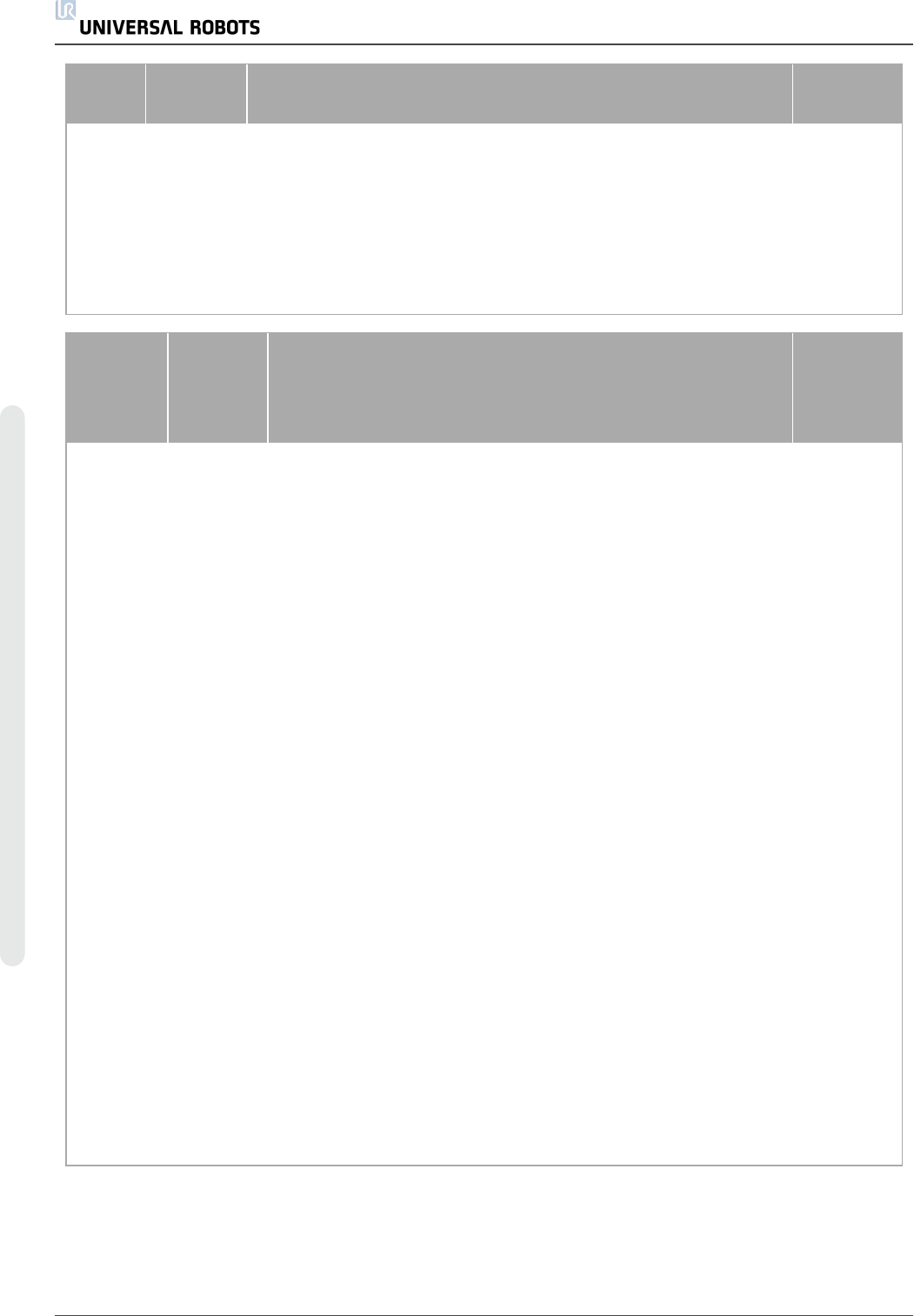
SF15
Internal
as a
function
with
dual
outputs
UR Robot
Not
Reduced
Mode:
Digital
Output
Whenever the robot is NOT in reduced mode, the dual digital
outputs are LOW. The functional safety rating is for what is within
the UR robot. The integrated functional safety performance
requires adding this PFHd to the PFHd of the external logic (if
any) and its components.
External
connection
to logic
and/or
equipment
TUV
NORD
Certified
SF
Safety
Function
Description
What is
controlled?
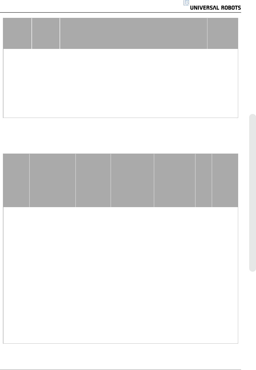
Robot
Reduced
Mode
Internal
Logic and
Outputs,
with Dual
Inputs (1
through 4)
Reduced Mode can be initiated by a safety plane/ boundary
(starts when at 2cm of the plane and reduced mode settings
are achieved within 2cm of the plane) or by use of an input to
initiate (will achieve reduced settings within 500ms). When the
external connections are Low, Reduced Mode is initiated.
Reduced Mode means that ALL reduced mode limits are
ACTIVE Reduced mode is not a safety function, rather it is a
state affecting the settings of the following safety function
limits: SF3 joint position, SF4 joint speed, SF6 TCP pose limit,
SF7 TCP speed, SF8 TCP force, SF9 momentum, and SF10
power.
Robot Arm
Safeguard
Reset
Internal
Logic and
Outputs,
with Dual
Inputs (1
through 4)
When configured for Safeguard Reset and the external
connections transition from low to high, the safeguard stop
RESETS Safety input to initiate a reset of safeguard stop
safety function SF2.
Robot
Enabling
Device
External
Enabling
Device as
input to
UR Robot
logic
When the external Enabling Device connections are Low, a
Safeguard Stop (SF2) is initiated. Recommendation: Use with
a mode switch as a safety input. If a mode switch is not used
and connected to the safety inputs, then the robot mode will be
determined by the User Interface. If the User Interface is in:
• “run mode”, the enabling device will not be active.
• “programming mode”, the enabling device will be active.
It is possible to use password protection for changing
the mode by the User Interface.
Robot
UR5 74 用 户 手 册
版 权所 有 © 2009–2021UniversalRobotsA/S。保留 所 有 权利。
TUV
NORD
Certified
SF
Safety
Function
Description
What is
controlled?
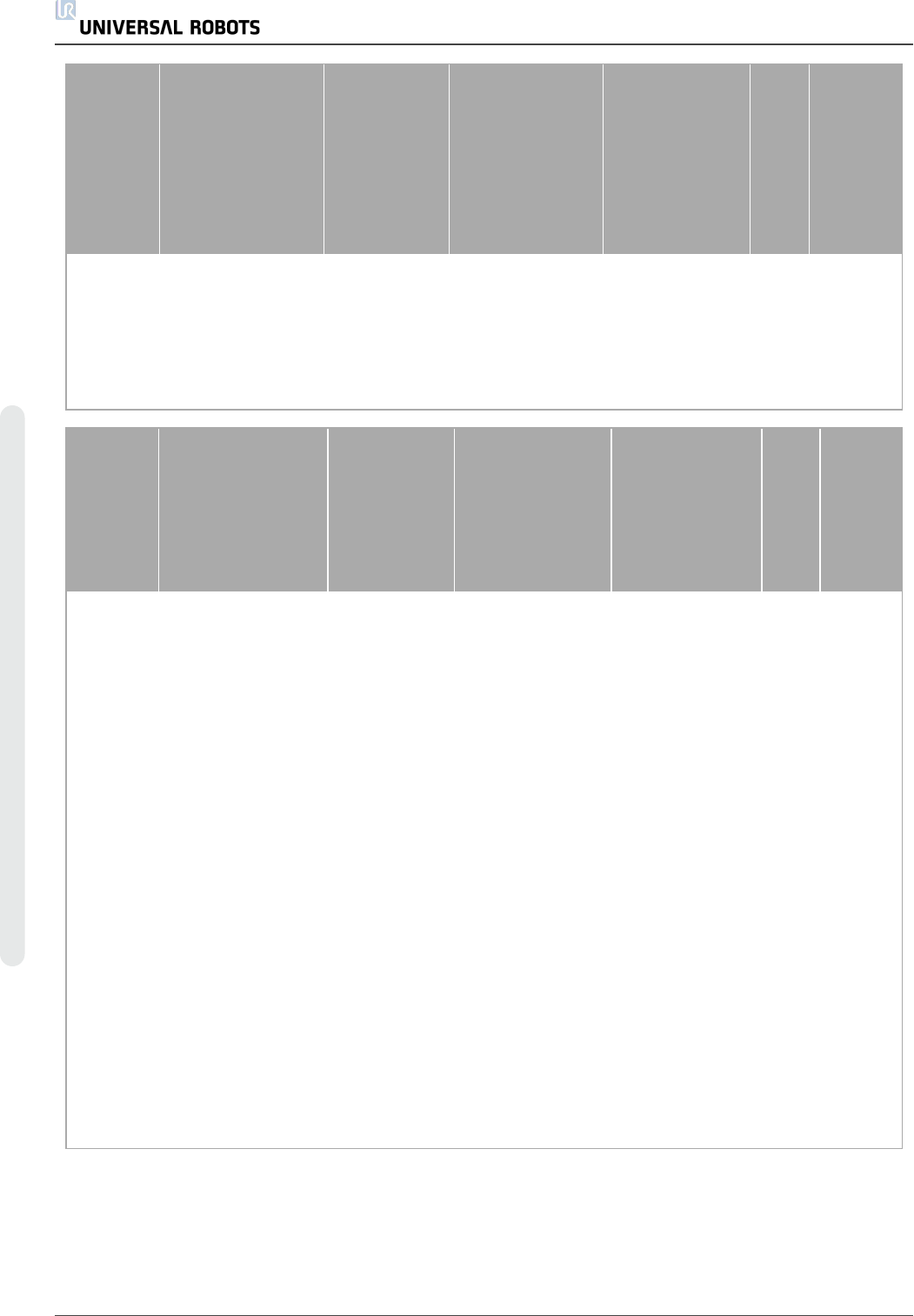
Mode
Selection
External
Mode
Switch
using dual
Inputs (1
through 4)
and
internal
logic
When the external connections are Low, Operation Mode
(running) is in effect. When High, the mode is programming or
teach. Must be used with an Enabling Device as a safety input.
When in Teach/Program (Mode switch inputs high), enabling
device is required for operation. When in teach/program,
initially the TCP speed will be limited to 250mm/s. The speed
can manually be increased by using the pendant user interface
“speed-slider”, but upon activation of the enabling device, the
speed limitation will reset to 250mm/s.
Robot
1.20. Table 2: Compliance and ISO 13849-1
Functional Safety Information
TUV
NORD
Certified
SF
Safety Function
Limits or
USER
configuration
or Factory
Setting
Stop Category
per IEC 60204-1
IEC 61800-5-2
Stop: power to
final switching
devices
retained for
Category 2
stop
PLd
Cat
PFHd
UR
3/5/10
SF0
Emergency Stop
There are two
separate
Emergency Stop
safety functions:
SF0 and SF1
No
Cat 1 Stop
524ms time-
delay before Cat
0 stop is initiated
NA 3 4.38E-8
SF1
Emergency Stop
There are two
separate safety
functions: SF0
and SF1
No
Cat 1 Stop when
at SS1 standstill,
Cat 0 stop
initiated
SS1 when at
SS1 standstill,
Cat 0 stop
initiated
2 3.16E-07
SF2
Safeguard stop
(Protective Stop)
No Cat 2 SS2 2 3.15E-07
SF3
Joint Position
Limit (soft axis
limiting)
Limits Cat 0 NA 2 3.15E-07
SF4 Joint Speed Limit Limits Cat 0 NA 2 3.15E-07
用 户 手 册 75 UR5
版 权所 有 © 2009–2021UniversalRobotsA/S。保留 所 有 权利。
TUV
NORD
Certified
SF
Safety Function
Limits or
USER
configuration
or Factory
Setting
Stop Category
per IEC 60204-1
IEC 61800-5-2
Stop: power to
final switching
devices
retained for
Category 2
stop
PLd
Cat
PFHd
UR
3/5/10
SF5
Joint Torque Limit
internal factory
setting
factory
setting
Cat 0 NA 2 3.15E-07
SF6 TCP Pose Limit Limits Cat 0 NA 2 3.15E-07
SF7 TCP Speed Limit Limits Cat 0 NA 2 3.15E-07
TUV
NORD
Certified
SF
Safety Function
Limits or
USER
configuration
or Factory
Setting
Stop Category
per IEC 60204-1
IEC 61800-5-2
Stop: power to
final switching
devices
retained for
Category 2 stop
PLd
Cat
PFHd
UR
3/5/10
SF8 TCP Force Limit Limits Cat 0 NA 2
3.15E-
07
SF9 Momentum Limit Limits Cat 0 NA 2
3.15E-
07
SF10 Power Limit Limits Cat 0 NA 2
3.15E-
07
SF11
UR RINPUTobot
Estop Output
Output & I/O
Configuration
See Estop SF1 See Estop SF1 2
4.41E-
08
SF12
UR Robot Moving:
Digital Output
Output & I/O
Configuration
Cat 0 NA 2
3.15E-
07
SF13
UR Robot Not
stopping:
Digital Output
Output & I/O
Configuration
Cat 0 NA 2
3.15E-
07
SF14
UR Robot
Reduced Mode:
Digital Output
Output & I/O
Configuration
Cat 0 if fault
detected
NA 2
3.15E-
07
SF15
UR Robot Not
Reduced Mode:
Digital Output
Output & I/O
Configuration
Cat 0 (immediate
stop)
NA 2
3.15E-
07
UR5 76 用 户 手 册
版 权所 有 © 2009–2021UniversalRobotsA/S。保留 所 有 权利。