Smart Gui - Algorithm Training Material_rev1.pdf - 第123页
Copyright © ViT rox All Rights Reserved . 123 T ake Note! ● Lead Height must set correctly ● The Lead Height set will be the reference height for lead. ● When Lead height measured > Lead Height set, Lifted Lead occur …
Copyright © ViTrox All Rights Reserved.
122
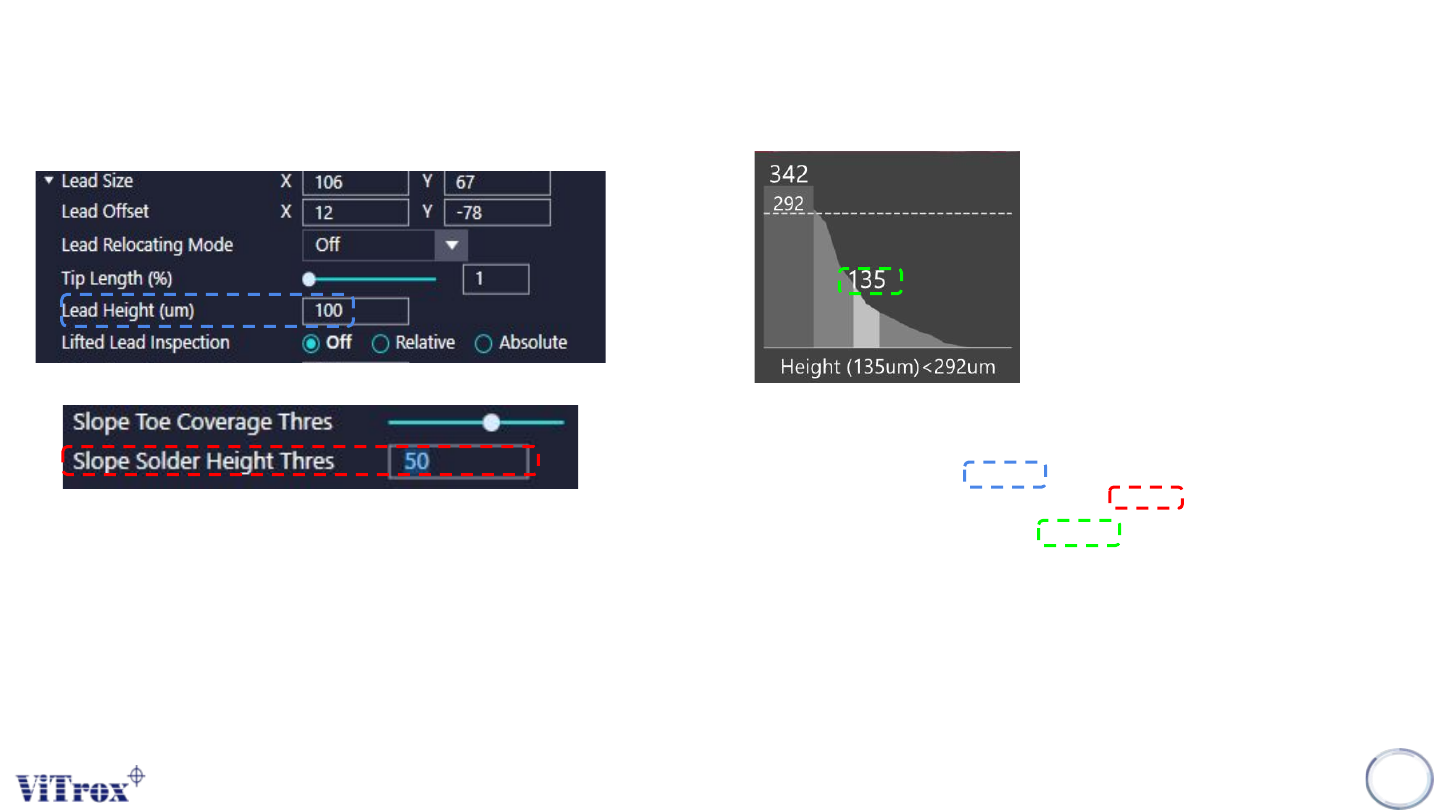
For this case:
Lead Height set to 100 um
Slope SolderHeight Thres set to 50 um
Measured Fillet height = 135 um
Measured Fillet Height > Fillet Height Thres
Why Failed???
S-type Algorithm - Joint (Solder Profile Inspection)
Copyright © ViTrox All Rights Reserved.
123
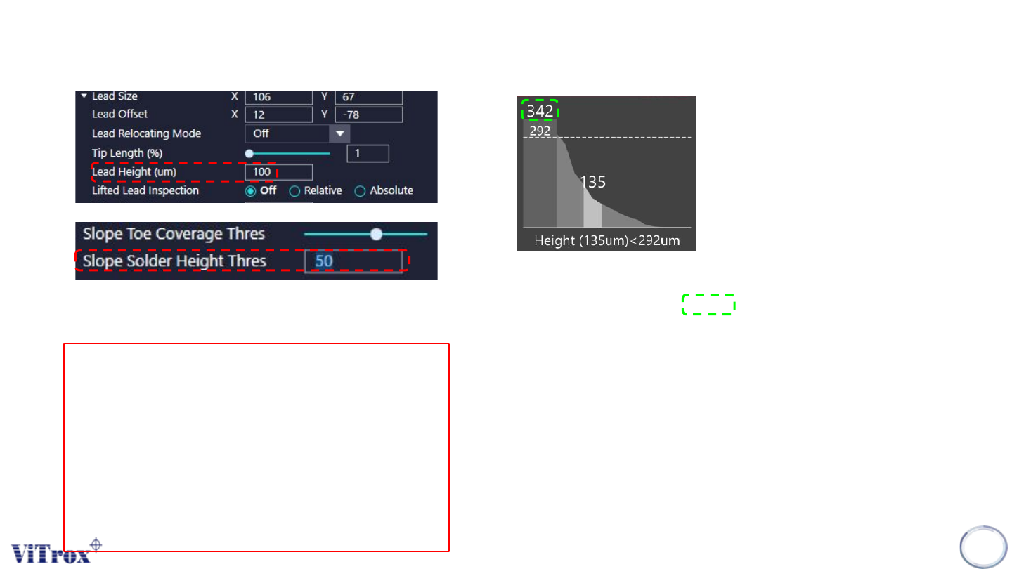
Take Note!
● Lead Height must set correctly
● The Lead Height set will be the reference
height for lead.
● When Lead height measured > Lead Height
set, Lifted Lead occur
● Results in the Slope Solder Height Thres
increased
● For component without led, body height will
replace lead height.
At the condition when:
Lead Height Measured = 342um
That’s mean the lead lifted by:
342um-100um = 242um
Results in
Slope Solder Height Thres = 50um (set) + 242um (Lifted)
= 292um
Therefore,
For any pixels with slope solder height > 292um only consider as
a pass pixel.
Lead Height set to 100 um & Slope Solder Height Thres set to 50um
S-type Algorithm - Joint (Solder Profile Inspection)
Copyright © ViTrox All Rights Reserved.
124
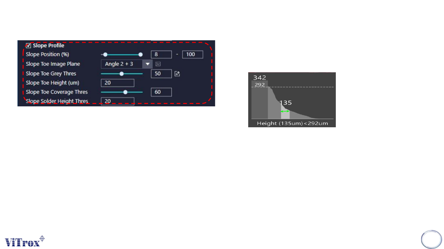
a. Slope Profile
● Enable or Disable Slope Profile Inspection.
b. Slope Position
● Location for slope profile inspection
c. Slope Toe Image Plane
● These are the types of 2D Lighting. Select the one with having
highest contrast among interested inspection region and the
background.
d. Slope Toe Grey Thres
● 2D Gray threshold to decide if there is excess solder at Toe area
e. Slope Toe Height
● Height threshold from PCB surface, to decide if there is solder at toe
area
f. Slope Toe Coverage Thres
● Threshold to qualify the coverage of solder at toe area
g. Slope Solder Height Thres
● Height threshold to qualify Solder Height Inspection
S-type Algorithm - Joint (Solder Profile Inspection)