Smart Gui - Algorithm Training Material_rev1.pdf - 第176页
Copyright © ViT rox All Rights Reserved . 176 U-T ype Diff Joint Algorithm Identify surface defects on component using certain parameter and through learning good components
Copyright © ViTrox All Rights Reserved.
U-type Locator - M Joint
175
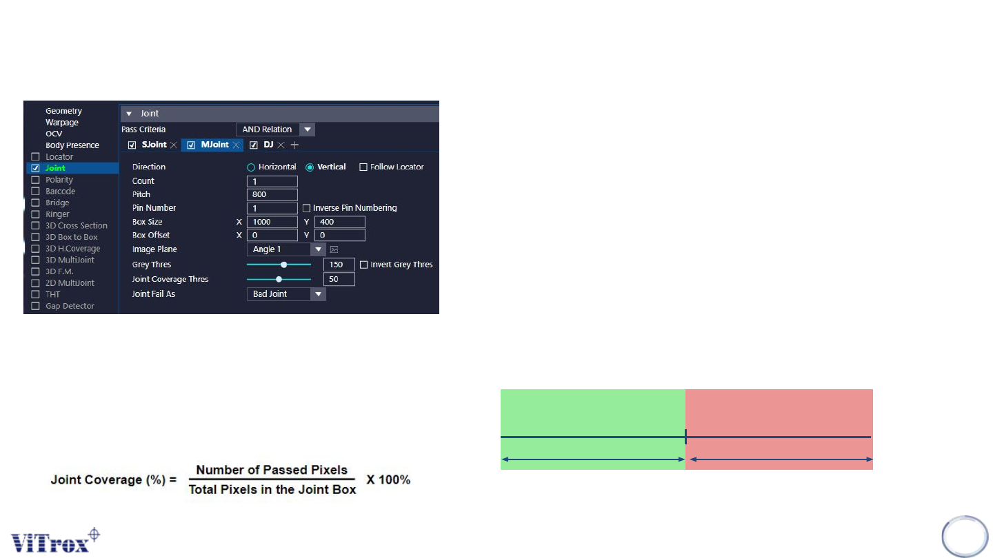
a. Direction
● Tick to enable the joint inspection box follow locator.
b. Count
● To adjust the number of pin.
c. Pitch
● To adjust the distance between the pins.
d. Pin Number
● To define the pin number
e. Inverse Pin Numbering
● To inverse the pin numbering.
f. Box Size & Box Offset
● To adjust the joint inspection box size & joint inspection box offset.
g. Image Plane
● These are the types of 2D Lighting. Select the one with having
highest contrast among interested inspection region and the
background.
h. Grey Thres
i. Invert Grey Thres
● Invert the Grey Thres Logic
● Dark: Fail & Bright: Pass
Grey Threshold
Pass Fail
Pass Criteria for single pixel:
a. Measured Grayscale < Joint Grey Thres
The overall pass criteria depends on:
Joint Coverage (%) > Joint Coverage Thres (%)
where,

Copyright © ViTrox All Rights Reserved.
176
U-Type Diff Joint Algorithm
Identify surface defects on component using certain parameter and
through learning good components
Copyright © ViTrox All Rights Reserved.
Steps for Diff Joint Learning Setup
177
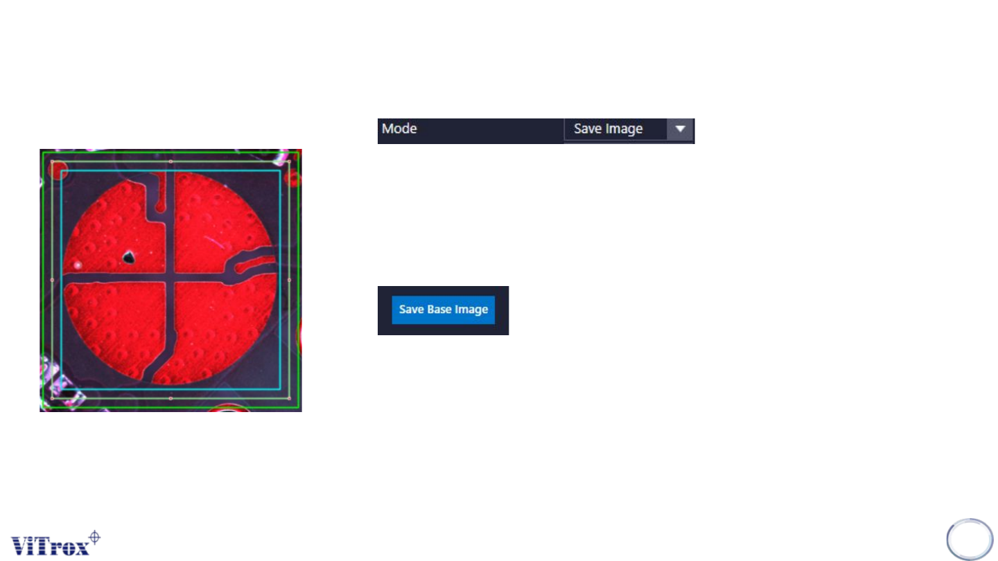
Step 1:
● Look for good sample & Select save image mode
Step 2:
● Drag and resize the box size & search box size
● Box Size: Interested region to save the base image.
● Search Box Size: Region to search the base image.
Step 3:
● Click on “Save Base Image”
Step 4:
● Press inspect button at 'Save Image' mode.
● This action is to save the good image of the component.
● A score will appear near the component. The score is indicate correlation
score.
Step 5:
● Do the save image step (Step 4) by at least 6 good components.
● After the last component is saved, change 'Save Image' mode to
'Inspect:xx' mode.
● This is to prevent if we accidently save defect component image.