Smart Gui - Algorithm Training Material_rev1.pdf - 第144页
Copyright © ViT rox All Rights Reserved . Lead Ringer - Parameter Description 144 5. Offset Along ● T o adjust the offset of ROI from the anchor point set. 6. Size Along ● T o adjust the size of ROI (Y -Direction). 7. Si…
Copyright © ViTrox All Rights Reserved.
Lead Ringer - Parameter Description
143
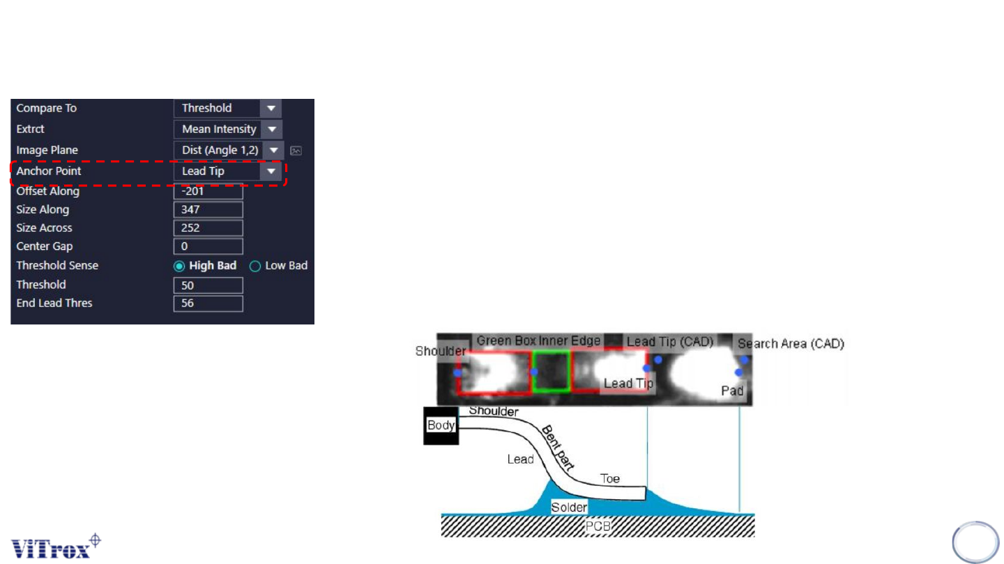
4. Anchor Point
● The region of inspection.
● The anchor points available in the Lead Ringer algorithm are as follow:
➔ Lead Tip anchor: (result of the lead location algorithm)
➔ Shoulder anchor: (result of the lead location algorithm)
➔ Lead Tip (Lock to Cad) anchor: (result of the geometry settings entered by the user, taking into
account the component position, number of leads, pitch, lead length, ...)
➔ Pad End (Lock to Pad) anchor: (result of the Pad Locator algorithm)
➔ Search Area End (Lock to Cad) anchor (similar as Lead Tip (Lock to Cad), but the point is
locked to the search area instead of being at lead tip)
➔ Green Box Inner Edge anchor: (result of lead location algorithm)
Copyright © ViTrox All Rights Reserved.
Lead Ringer - Parameter Description
144
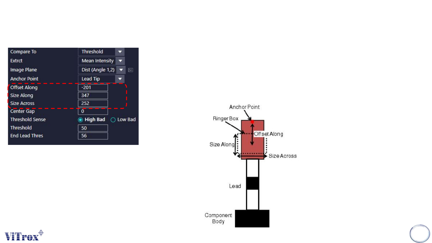
5. Offset Along
● To adjust the offset of ROI from the anchor point set.
6. Size Along
● To adjust the size of ROI (Y-Direction).
7. Size Across
● To adjust the size of ROI (X-Direction).
Copyright © ViTrox All Rights Reserved.
Lead Ringer - Parameter Description
145
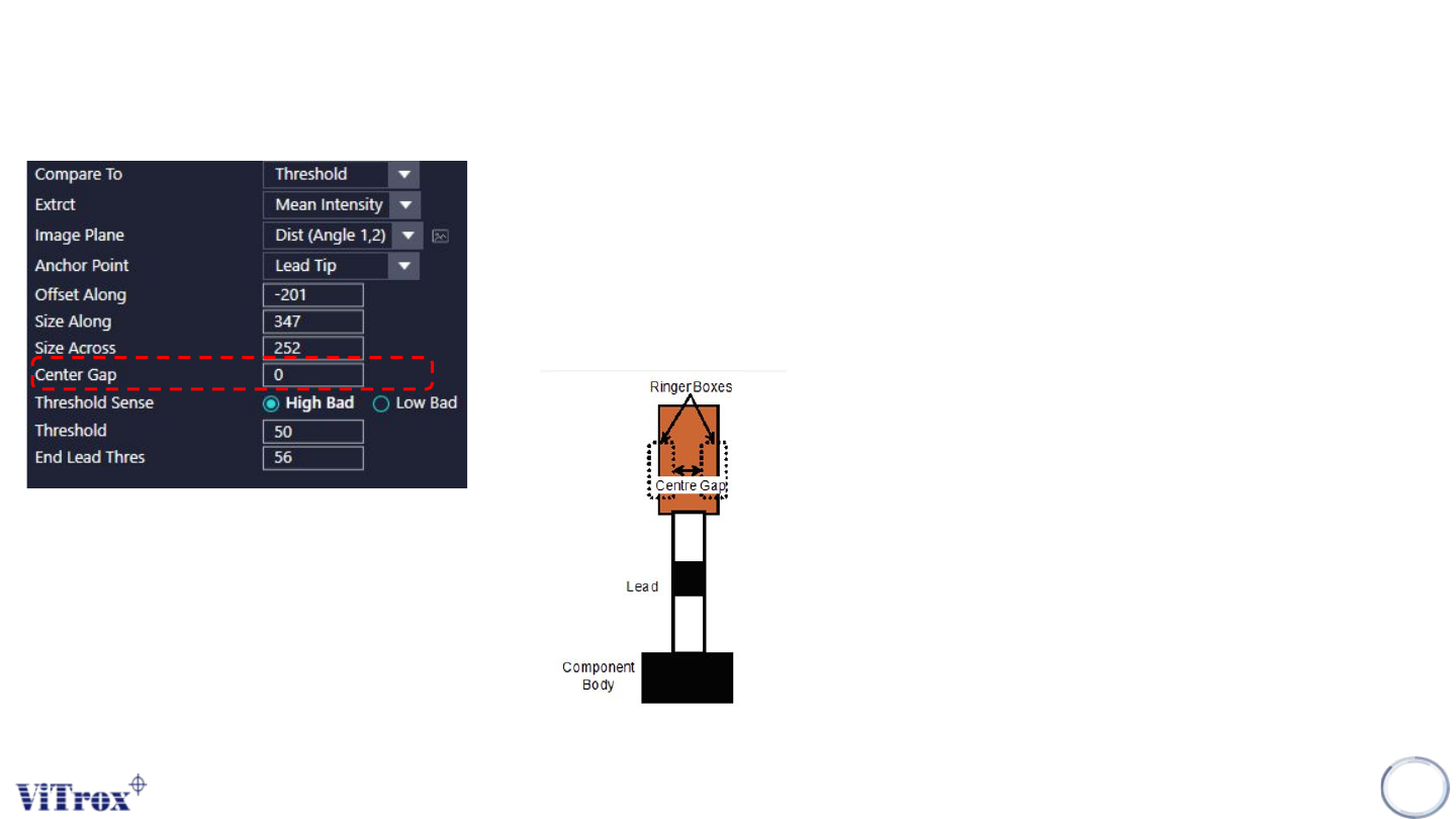
8. Centre Gap
● Enables the user to separate the ringer box into two for each lead.
● The RInger comparison will be carried on the resulting sum of the values with those two boxes.
● The Centre Gap option is used when a change appears on the sides of the lead/solder areas, or when an
unwanted reflection is present in the middle of the lead width.
● Note that inserting a centre gap different from zero should lead to a revision of the current thresholds.