Smart Gui - Algorithm Training Material_rev1.pdf - 第231页
Copyright © ViT rox All Rights Reserved . U-type Algorithm - THT 231 1. Detecting insufficient solder fillet. 2. Detecting NO SOLDER which leave the HOLE exposed. 3. Hole Region = Region within Green box & Magenta bo…
Copyright © ViTrox All Rights Reserved.
U-type Algorithm - THT
230
Pin Tip Region
(White)
Pin Chamfer Region
(Gray)
Top View Size View
1. When lighting projected on the pin,
● Pin tip region will be bright.
● Pin chamfer region will be dark.
● This is due to the reflection of ght.
2. Pin Tip region will be the region for the locator to locate the pin.
3. Pin Region = Pin Tip region + Pin Chamfer region
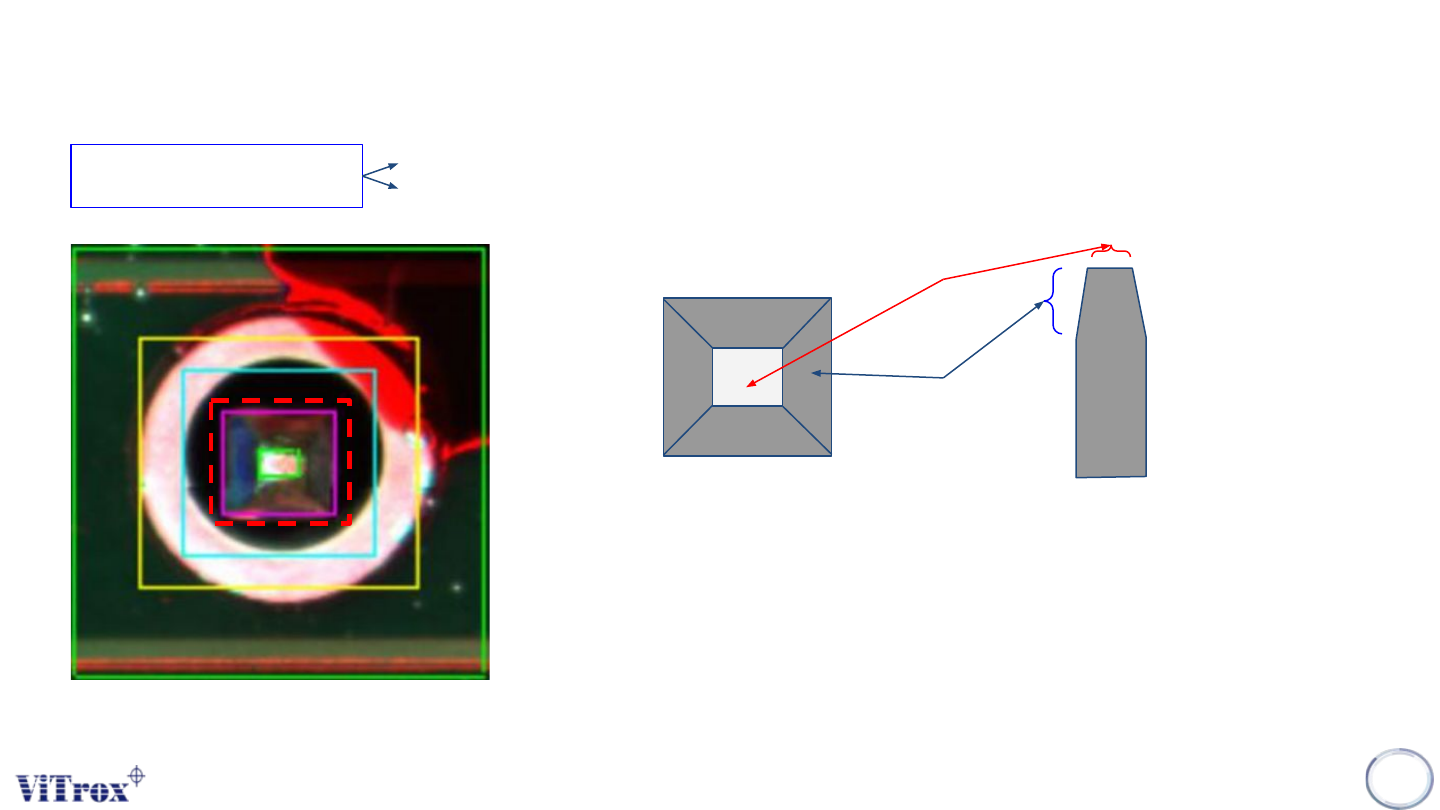
Pin Region
1. Locate the pin location
2. Detect the existing of pin.
Copyright © ViTrox All Rights Reserved.
U-type Algorithm - THT
231
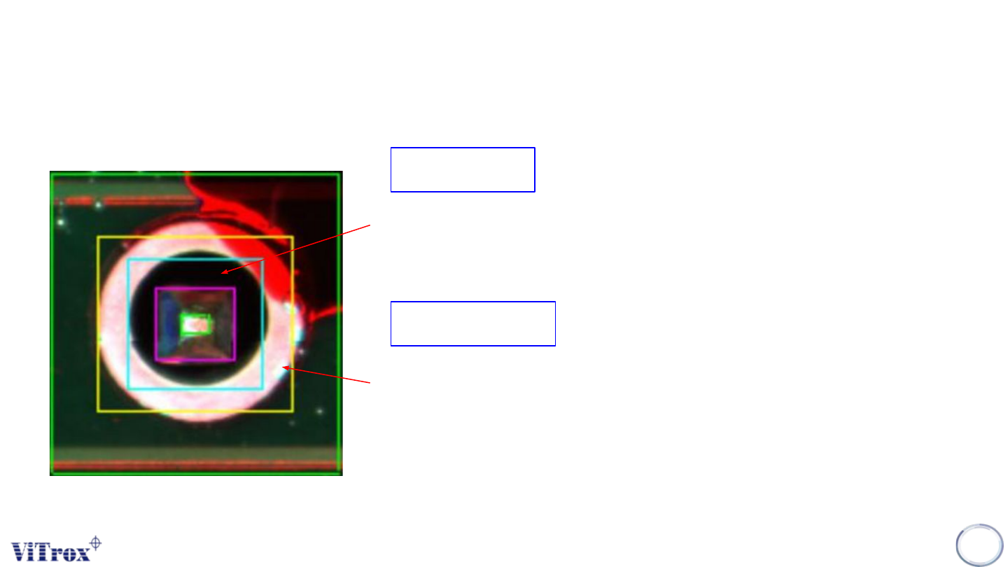
1. Detecting insufficient solder fillet.
2. Detecting NO SOLDER which leave the HOLE exposed.
3. Hole Region = Region within Green box & Magenta box.
Hole Region
Solder Region
1. Detecting insufficient solder.
2. Detecting exposed pad
3. Solder Region = Region within yellow box and blue box.
Copyright © ViTrox All Rights Reserved.
U-type Algorithm - THT
232
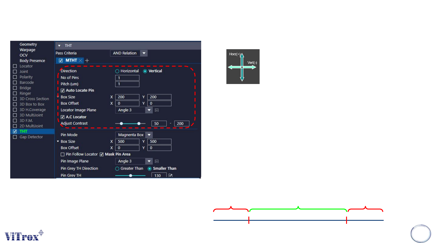
a. Direction
● To adjust the direction for multiple pins.
b. No of Pins
● To adjust the number of pins.
c. Pitch
● To adjust the distance between 2 pins.
d. Auto Locate Pin
● Enable this to set the locator to locate the pin.
e. Box Size & Box Offset
● To adjust the size and offset for locator inspection box.
f. Locator Image Plane
● These are the types of 2D Lighting. Select the one with having highest
contrast among pin tip region and the background.
g. A.C Locator
● Tick this to enable adjust contrast for the selected image plane.
● If contrast set to 50 to 100:
Remain the Greyscale Become 255
Become 0
50 100