Smart Gui - Algorithm Training Material_rev1.pdf - 第8页
Copyright © ViT rox All Rights Reserved . CR T ype Algorithm - Locator 8 1. 2D Locator ● Only use 3D to locate the component location. ● Only use 2D to locate the component location. ● Select this to enable 2D + 3D Locat…
Copyright © ViTrox All Rights Reserved.
CR Type Algorithm - Locator
7
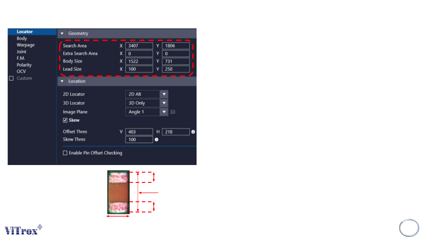
1. Search Area
● Adjust the XY Dimension for the green box.
● Component will be find within the search area.
2. Extra Search Area
● Extra Search Area is used to force a component towards
the center of the field of view. (Units:micron)
● The Search area extra specifies are area around a
components search are which cannot be allowed to fall at
the edge of the field of view. This could be used for
components which appear different at the edge of the field
of view, e.g. tall components.
● It has a maximum value of 20000. A typical value is 15000.
3. Body Size
● Adjust the XY Dimension for the blue box.
● Component XY Dimension.
● Right click on the component and select “Auto Fill Body” to
auto set the body size.
4. Lead Size
● Setup the lead XY measurement value when enable 2D
locator mode.
Lead size X
Lead size X
Body size X
Lead size Y = Body size Y
Copyright © ViTrox All Rights Reserved.
CR Type Algorithm - Locator
8
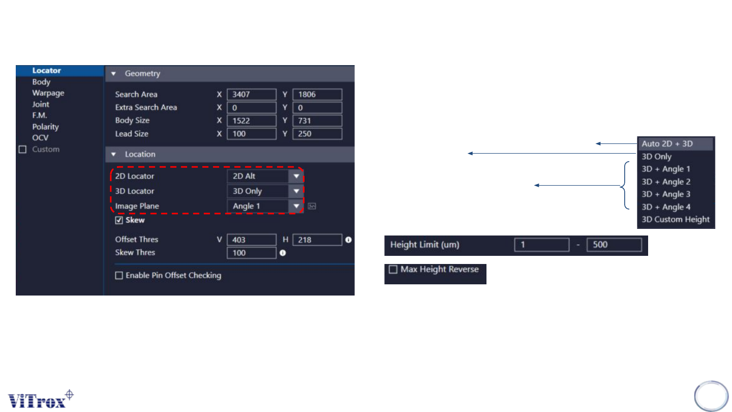
1. 2D Locator
● Only use 3D to locate the component location.
● Only use 2D to locate the component location.
● Select this to enable 2D + 3D Locator
● 3D as priority, 2D to support
3. Image Plane
● These are the types of 2D Lighting. Select the one
with having highest contrast among interested
inspection region and the background.
2. 3D Locator
● Auto select 2D or 3D (Whichever is better)
● Only use 3D
● Only use 3D, The height range can be preset as
below.
Max Height Reverse means Change the max
height to min height.
Copyright © ViTrox All Rights Reserved.
CR Type Algorithm - Locator
9
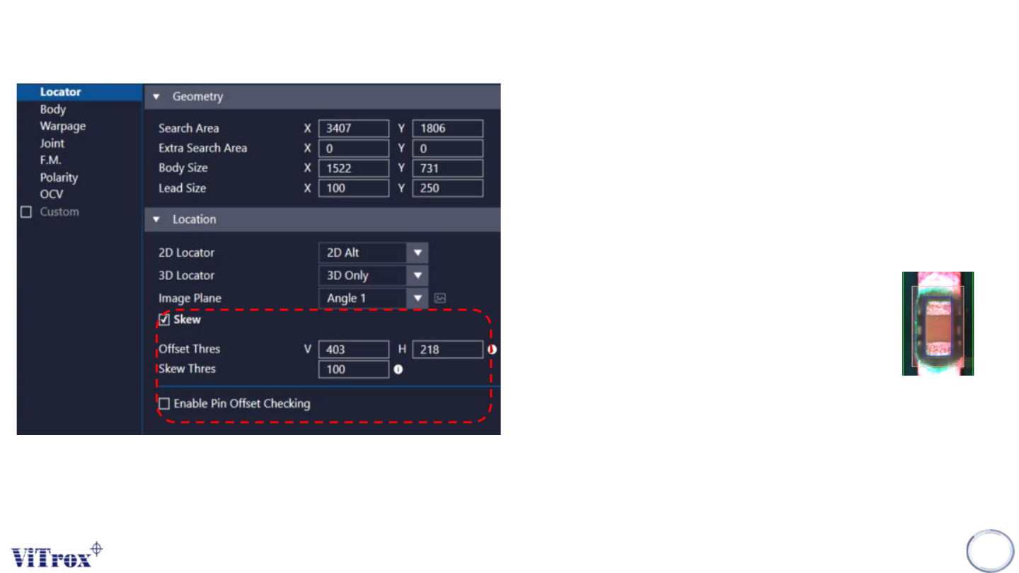
1. Skew
● Tick this to include skew inspection
2. Offset Thres
● To preset the allowed value for offset. The pink
colour box below shows the acceptable offset
area. User may drag to adjust the box size.
3. Offset Box
● If the component out of this area will fail
the inspection result.
4. Skew Thres
● To set the skew threshold in degree.
● Will fail the inspection when:
measured skew value > Skew Thres
● 1 = 0.1 deg