Smart Gui - Algorithm Training Material_rev1.pdf - 第237页
Copyright © ViT rox All Rights Reserved . U-type Algorithm - THT 237 h. Coverage Algo 3D Mode ● Using 3D (Height V alue) to determine the coverage of solder . i. Height Thres Range ● E.g. Height Thres Range set to 20 to …
Copyright © ViTrox All Rights Reserved.
U-type Algorithm - THT
236
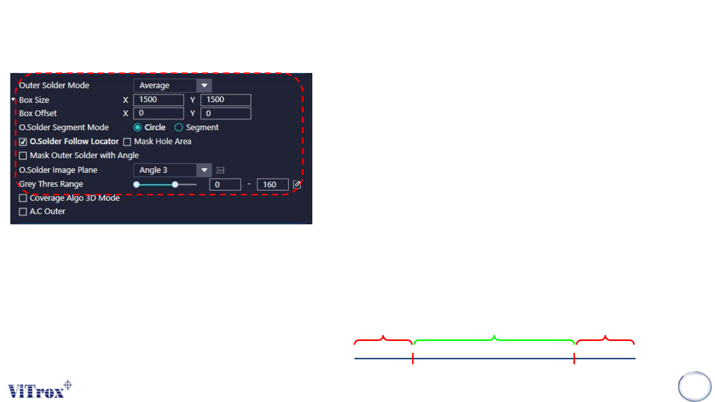
a. Outer Solder Mode
● Average -
● Coverage -
b. Box Size & Box Offset
● To adjust the size and offset for Hole Solder inspection box.
c. O. Solder Segment Mode
● Circle - Use circle region in the calculation
● Segment - Use 8 segment region in the calculation
d. O. Solder Follow Locator
● Tick to enable the Outer solder inspection box follow the locator.
e. Mask Hole Area
● Tick to mask to Hole Area during outer solder inspection.
f. O. Solder Image Plane
● These are the types of 2D Lighting. Select the one with having highest
contrast among Hole Solder region and the background.
g. Grey Thres Range
● Hole Inspection will fail if the measured Grey Thres on that particular
pixel out of the Threshold range set.
● E.g. Grey Thres Range from 50 to 200
Pass Fail
Fail
50 200
Copyright © ViTrox All Rights Reserved.
U-type Algorithm - THT
237
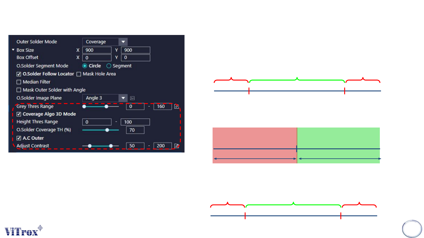
h. Coverage Algo 3D Mode
● Using 3D (Height Value) to determine the coverage of solder.
i. Height Thres Range
● E.g. Height Thres Range set to 20 to 100
Pass Fail
Fail
20 100
j. O.Solder Coverage TH (%)
● The percentage of coverage based on pixels.
Solder Coverage
Threshold
PassFail
k. A.C Outer
● Tick to enable the adjust contrast for the selected image plane.
Remain the Greyscale Become 255
Become 0
50 200
Copyright © ViTrox All Rights Reserved.
U-type Algorithm - THT
238
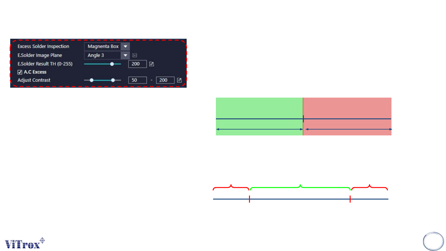
a. Excess Solder Inspection
● Magenta Box - Region within Magenta Box & Yellow Box
● Cyan Box - Region Within Cyan Box & Yellow Box
b. E.Solder Image Plane
● Select Image Plane for Excess Solder algorithm
c. E.Solder Result TH
d. A.C Excess
● Tick to enable the adjust contrast for the selected image plane.
Excess Solder Result TH
Pass Fail
Remain the Greyscale Become 255
Become 0
50 200