00198661-02_UM_SX12-V3_EN.pdf - 第109页
Instruction manual SIPLACE SX1/SX2 Edition V2 and V3 3 Technical data and assemblies From software version SC.713.1 Edition 12/2020 3.4 Ambient condit ions and connection values 109 3.4.4 Electrical ratings and energy co…
3 Technical data and assemblies Instruction manual SIPLACE SX1/SX2 Edition V2 and V3
3.4 Ambient conditions and connection values From software version SC.713.1 Edition 12/2020
108
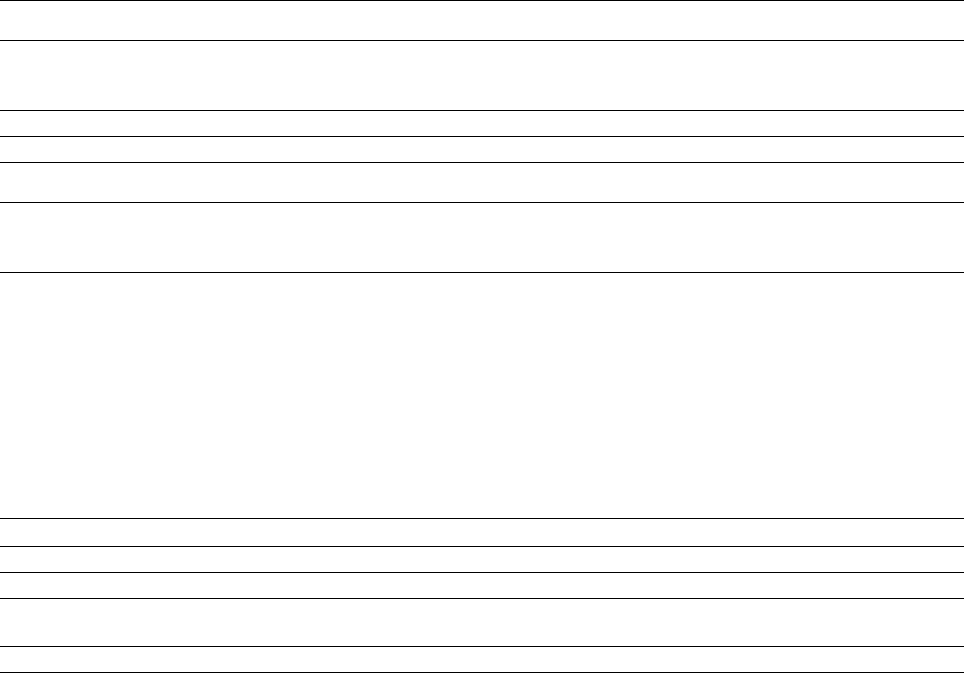
3.4.3 Compressed air supply and compressed air specification
3
3
Compressed air supply
Compressed air pressure values
p
min
p
max
0.5 MPa = 5.0 bar
1.0 MPa = 10 bar
Operating pressure 0.48 MPa ± 0.025 MPa (4.8 bar ± 0.25 bar)
Compressed air connection R 3/4" inner thread (pipe thread) with 1/2" hose connection
Compressed air consumption
*a
Placement head configura-
tion
Compressed air
consumption
with vacuum pumpd
*b
Compressed air
consumption
without vacuum pump
*c
SIPLACE SX2
SIPLACE SX1
C&P20 P2 / C&P20 P2
C&P20 P / C&P20 P
CPP / CPP
CPP / TH
TH / TH
C&P20 P2
C&P20 P
CPP
TH
200 Nl/min
200 Nl/min
--
--
--
100 Nl/min
100 Nl/min
--
--
490 Nl/min
490 Nl/min
240 Nl/min
240 Nl/min
200 Nl/min
280 Nl/min
280 Nl/min
140 Nl/min
100 Nl/min
Compressed air specification according to ISO 8573
Particle size (ISO class 3) 5 µm
Particle density (ISO class 3) 5 mg/m³
Maximum oil content
(ISO class 1)
Particle density 0.01 mg/
m³
Pressure dewpoint (ISO class 4) Dewpoint + 3°
*)a Average consumption values. Under normal atmospheric conditions at 20°C and 1013 hPa
*)b Vacuum pump only for the C&P20 P2 or the C&P20 P.
*)c Standard
Instruction manual SIPLACE SX1/SX2 Edition V2 and V3 3 Technical data and assemblies
From software version SC.713.1 Edition 12/2020 3.4 Ambient conditions and connection values
109
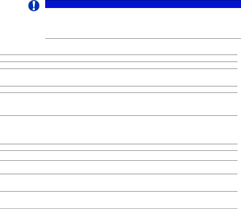
3.4.4 Electrical ratings and energy consumption
3
3
3
PLEASE NOTE
Use of a residual current protection device
The low ground leakage current of the system makes it possible to use an upstream
residual current protection device at the customer end. This must be all-current sen-
sitive (RCD type B).
Electrical ratings
Supply voltage
Main power supply 3/N/PE ~ 380 V / 220 V to 415 V / 240 V ± 10 %; 50/60 Hz
3/N/PE ~ 200 V / 115 V to 220 V / 127 V ± 10 %; 50/60 Hz
*a
3/PE ~ 200 V to 220 V ± 10 %; 50/60 Hz
a
Fuse
Full load current 3.5 A - 2.2 A / phase
*b
6.3 A - 4.4 A / phase
b
6.3 A - 4.4 A / phase
b
3 x 16A characteristic C
*c
3 x 15 A characteristic C
c
3 x 15 A characteristic C
c
Mains power connection Without cable
Cable 5 x 4,0 mm² WITH CEE plug, red 16 A (in accordance with IEC 60309) (3 x 380 V~ to
3 x 415 V~)
Cable 5 x 4.0 mm² WITHOUT plug (3 x 200 V~ to 3 x 220 V) or
(3 x 380 V~ to 3 x 415 V~)
Short circuit classification of machine (SCCR)
*d
10 kA
Energy consumption
Energy consumption
with vacuum pump
*e
Energy consumption
without vacuum pump
*f
Average apparent power
SIPLACE SX1
SIPLACE SX2
3.2 kVA
3.8 kVA
2.0 kVA
2.6 kVA
Average effective power
SIPLACE SX1
SIPLACE SX2
2.0 kW
2.4 kW
1.2 kW
1.6 kW
*)a With options package
*)b Selection of customer's supply voltage range.
*)c For example: Siemens circuit breakers in accordance with UL 489 and IEC (order no.: 5SJ4 316-7HG42)
or
EATON Industries circuit breaker FAZ-C16/3-NA 16A 3p (UL 489, CSA C22.2 no. 5, IEC 60947-2)
*)d With the original mains connection cable. The marked short circuit rating (SCCR) relates to the beginning of the original
mains cable. In the case of customer modifications, the factory-set length of the mains cable to the machine may not be
shortened nor the factory-set conductor cross-section increased, as this would have a negative impact on the short circuit
rating (SCCR).
*)e Vacuum pump for C&P20 P2 head only (optional).
*)f Standard

3 Technical data and assemblies Instruction manual SIPLACE SX1/SX2 Edition V2 and V3
3.5 Dimensions and weight From software version SC.713.1 Edition 12/2020
110
3.5 Dimensions and weight
3.5.1 Technical data - dimensions and weight
3
Length of placement machine
SX1/SX2 1500 mm
Width of placement machine
SX1/SX2
*a
2475 mm
Height of placement machine
With indicator lamp
With folded-up protective covers
(for PCB conveyor height 900 mm)
(for PCB conveyor height 930 mm)
(for PCB conveyor height 950 mm)
max. 1765 mm
1980 mm
2010 mm
2030 mm
Floor clearance of placement machine
(for PCB conveyor height 900 mm)
(for PCB conveyor height 930 mm)
(for PCB conveyor height 950 mm)
120 mm ± 15 mm
150 mm ± 15 mm
170 mm ± 15 mm
Weight of SX
*b
SX1 with 2x component trolley 60
SX1 with 2x component trolley 60 (fully configured)
SX2 with 2x component trolley 60
SX2 with 2x component trolley 60 (fully configured)
2482 kg
2806 kg
2532 kg
2856 kg
Floor space for SX
a
SX1/SX2 with 2x component trolley 60 3.71 m²
The load per unit area calculation included an additional working space
of 0.5 m on each side of the machine.
Load per unit area for SX
c
SX1
SX2
6.1 kN/m²
6.2 kN/m²
The load per unit area calculation includes an additional working space
of 1.0 m on each side of the machine.
Load per unit area for SX
c
SX1
SX2
4.7 kN/m²
4.8 kN/m²
Number of machine feet 4
*)a Standard configuration: 1 component trolley inside and 1 component trolley outside with handles folded down.
*)b Standard configuration: 1 component trolley inside, 1 component trolley outside and single conveyor.