00198661-02_UM_SX12-V3_EN.pdf - 第130页
3 Technical data and assemblies I nstruction manual SIPLACE SX1/S X2 Edition V2 and V3 3.7 Placement head From software version SC.713.1 Edition 12/2020 130 3 Fig. 3.7 - 7 SIPLACE MultiSt ar CPP - ba ck view , function g…
Instruction manual SIPLACE SX1/SX2 Edition V2 and V3 3 Technical data and assemblies
From software version SC.713.1 Edition 12/2020 3.7 Placement head
129
3
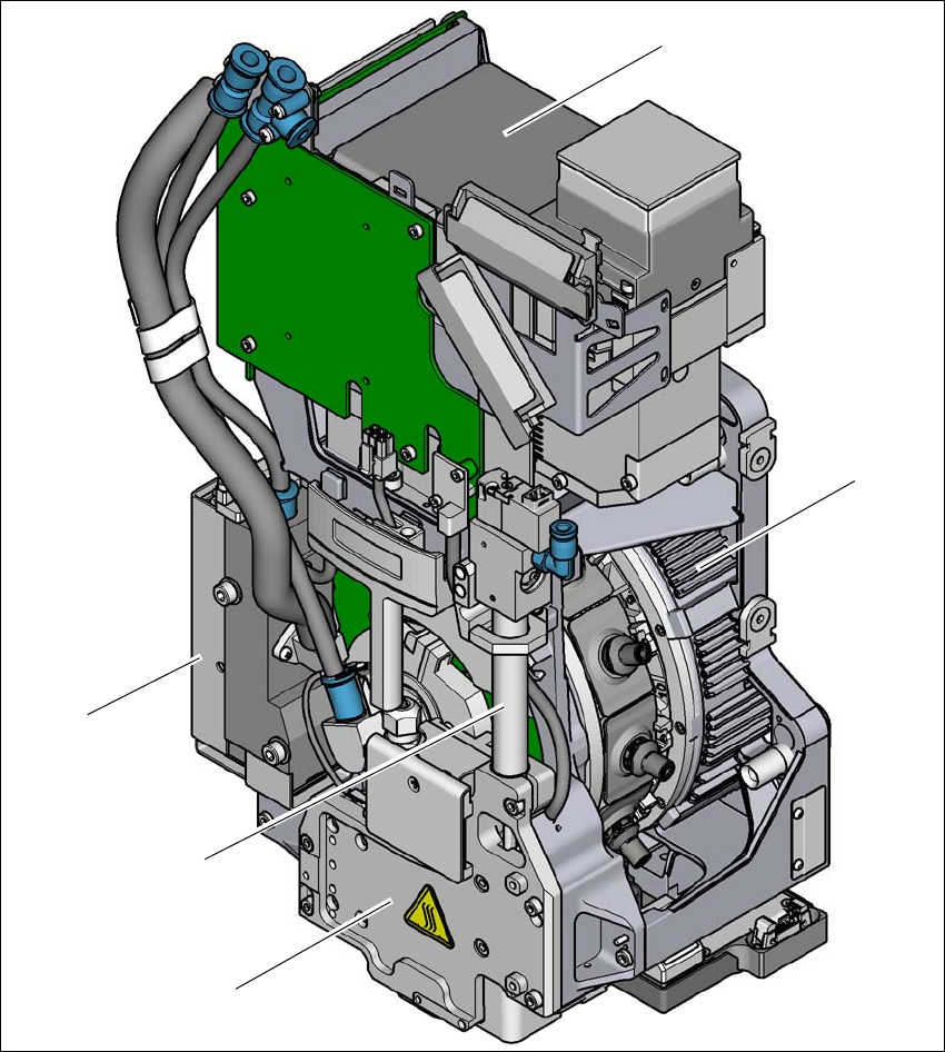
Fig. 3.7 - 6 SIPLACE MultiStar CPP - front view, function groups part 2
(1) Component camera C&P, type 30 GigE
(2) Torque motor for star drive
(3) Z drive (linear motor)
(4) Return cylinder
(5) Pressure control valve
(1)
(2)
(3)
(4)
(5)
3 Technical data and assemblies Instruction manual SIPLACE SX1/SX2 Edition V2 and V3
3.7 Placement head From software version SC.713.1 Edition 12/2020
130
3
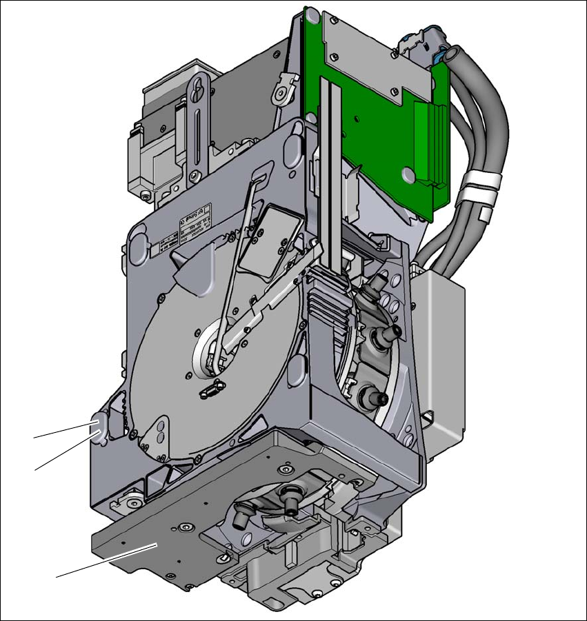
Fig. 3.7 - 7 SIPLACE MultiStar CPP - back view, function groups part 3
(1) Component sensor
(2) Assembly position for component height of up to 15,5 mm
(3) Assembly position for component height of up to 6 mm
(3)
(2)
(1)

Instruction manual SIPLACE SX1/SX2 Edition V2 and V3 3 Technical data and assemblies
From software version SC.713.1 Edition 12/2020 3.7 Placement head
131
3.7.5.1 Assembly positions of SIPLACE MultiStar
The SIPLACE MultiStar CPP head can be fitted to the head mount in two different positions:
– MultiStar in the top assembly position
In this position, all components can be processed up to a size of 50 mm x 40 mm and a
height of 15.5 mm.
3
– MultiStar in the bottom assembly position
In this position, the CPP head places components up to a size of
27 mm x 27 mm and a component height of 6 mm, using the Collect&Place method.
3
Observe the following rules when defining the assembly position:
The head height must be the same for all heads in the same placement area.
Always install the SIPLACE Multistar CPP head in the top assembly position if it is to be com-
bined with the following assemblies:
– Stationary component camera
– Waffle pack changer (WPC5/WPC6)
–TwinStar
3.7.5.2 Classification of component range to be processed
3
Component
class
Component
size
Assembly
position
*a
of CPP
head
Component
height
Component
camera type
Small compo-
nent
K_BE
03015 -
27 mm x 27 mm
Top Up to 8.5 mm
Head camera,
type 30
Bottom Up to 6.0 mm
Medium sized
component, type
M_BE_1
< 27 x 27 mm
Top
Between 8.5 and
11.5 mm
Stationary compo-
nent camera,
type 33
Bottom Not possible
Medium sized
component, type
M_BE_2
Between
27 mm x 27 mm
and
32 mm x 32 mm
Top 11.5 mm
Bottom Not possible
Large compo-
nent
G_BE
Between
32 mm x 32 mm
and
50 mm x 40 mm
Top Up to 15.5 mm
Stationary compo-
nent camera,
type 33
Bottom Not possible
Tab. 3.7 - 1Classification of component range to be processed
*)a Please observe the rules for assembly position heights in section 3.7.5.1
, page 131.