00198661-02_UM_SX12-V3_EN.pdf - 第196页
4 Setting up and commissioning Instruction manual SIPLACE SX1/SX 2 Edition V2 and V3 4.2 Infrastructure at the installation location From software ve rsion SC.713.1 Edition 12/2020 196 4.2.3.3 Main supply - specification…
Instruction manual SIPLACE SX1/SX2 Edition V2 and V3 4 Setting up and commissioning
From software version SC.713.1 Edition 12/2020 4.2 Infrastructure at the installation location
195
4
4.2.3.2 Checking the main power supply
Check whether the power supply complies with the prescribed machine specifications (see table
in section 3.4
, page 107).
4
DANGER
Lethal voltages under the safety cutoff (CSB) cover!
Under the cover there are components which could still carry lethal voltages for a certain
time, even when the placement machine is switched off and the mains plug has been dis-
connected. After disconnecting the mains plug, wait 5 minutes until the capacitors have
discharged.
Never open the covers.
Only ASM Assembly Systems GmbH&Co.KG service engineers or the machine
owner's service engineers, who have been trained by ASM, may perform work on the
power supply and the safety cutoff (CBS).
PLEASE NOTE
Load peaks in power supply
For technical reasons, load peaks occur in the power supply.
Please contact your power company to clarify the mains impedance, if necessary.
4 Setting up and commissioning Instruction manual SIPLACE SX1/SX2 Edition V2 and V3
4.2 Infrastructure at the installation location From software version SC.713.1 Edition 12/2020
196
4.2.3.3 Main supply - specification
The following configurations are possible for the mains connection cable:
(1) Without
mains connection cable
(2) 5 x 4 mm² WITH CEE plug; red 16 A (in accordance with IEC 60309),
for 3 x 380 V~ to 3 x 415 V ± 10 %, 50/60 Hz mains voltage
(3) 5 x 4 mm² WITHOUT plug, for 3 x 200 V~ to 3 x 220 V~ ± 10 %; 50/60 Hz, or 3 x 380 V~ to
3 x 415 V ± 10 %, 50/60 Hz mains voltage
The color coding for the wires will depend on the country in which the system is operated.
4
4
WARNING
Cross-section and length of mains connection cable
The cross-section and length of the mains connection cable influence the Short-Circuit-
Current-Rating (SCCR) of the
placement machine.
When replacing the mains connection cable, do not increase the cross-section of the
wires or shorten the length of the cable.
WARNING
Clear marking of electrical leads!
The electrical leads to each individual placement machine and to the options installed
must be clearly labeled and easily assignable.
The regulations of the country in which the placement machine is operated apply.
Instruction manual SIPLACE SX1/SX2 Edition V2 and V3 4 Setting up and commissioning
From software version SC.713.1 Edition 12/2020 4.2 Infrastructure at the installation location
197
4.2.3.4 Mains connection - WITHOUT mains connection cable (configuration 1)
The placement machine has NO mains connection cable with it on delivery. The mains connection
cable is connected to the mains connection terminal (X94) in the power supply unit.
4
4
4
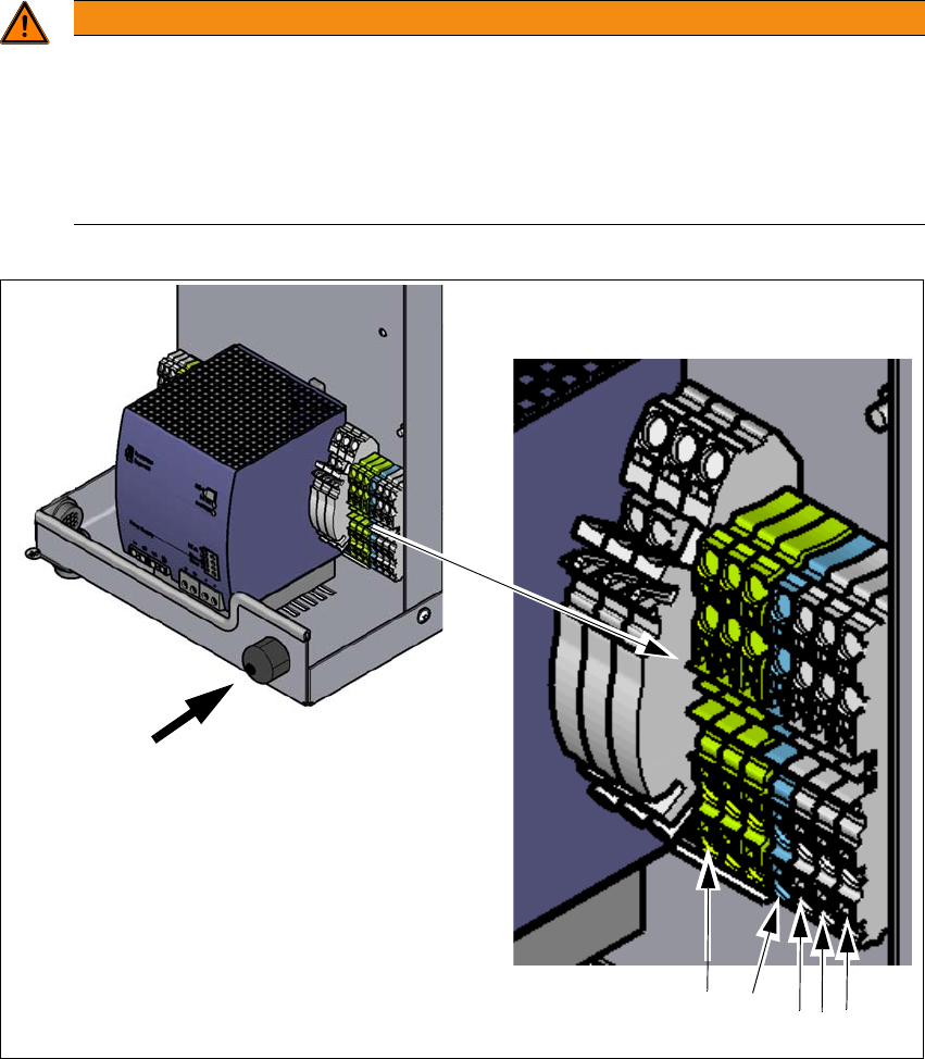
Fig. 4.2 - 4 Terminal panel for connecting the power cable
(1) Mains connection terminals (X94) for the mains power cable L1, L2, L2, N and PE The con-
nection terminals are designed for a wire diameter of 4 mm².
(2) Opening on the power supply with cable fixture
WARNING
The mains connection cable may only be connected by a qualified electrician.
The mains connection cable may only be connected by a qualified electrician. A qualified
electrician is a person with suitable professional qualifications, knowledge and experi-
ence, who is able to recognize hazards caused by electrical power and also prevent
these hazards from arising.
The regulations of the country in which the placement machine is operated apply.
(2)
(1)
L1
L2
L3
N
PE