00198661-02_UM_SX12-V3_EN.pdf - 第218页
4 Setting up and commissioning Instruction manual SIPLACE SX1/SX 2 Edition V2 and V3 4.3 Setting up the placement machine From software version SC.71 3.1 Edition 12/2020 218 4 Fig. 4.3 - 9 Measuring points on the placeme…

Instruction manual SIPLACE SX1/SX2 Edition V2 and V3 4 Setting up and commissioning
From software version SC.713.1 Edition 12/2020 4.3 Setting up the placement machine
217
4
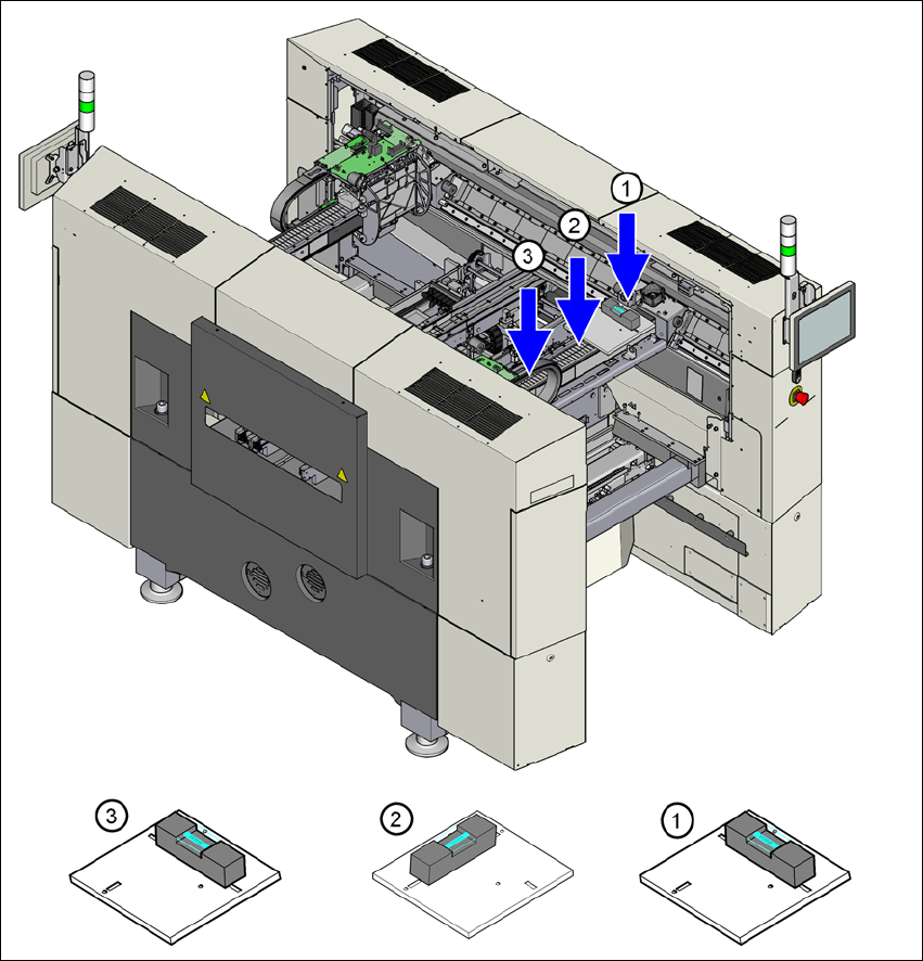
Adjust the placement machine by following the instructions below in the order listed:
(1) Align the placement machine in the Y direction at the fixed and loose bearing sides. The mea-
suring tolerance is 0.10 mm.
(2) Align the placement machine in the X direction to the middle of the gantry. The measuring
tolerance is 0.10 mm.
(3) Check the load-bearing strength of the 4 machine feet. The 4 machine feet must touch the
ground and be evenly loaded.
(4) Tighten the machine feet at the clamping screw to a torque of 130 Nm.
(5) Hit the feet with a hammer to check the load-bearing strength of the machine feet.
(6) Use the spirit level to ensure that the placement machine is precisely aligned.
PLEASE NOTE
Guaranteed handling accuracy of machine spirit level
Make sure that the spirit level is always placed onto the support plate the same way
round when measuring the X and Y directions
4 Setting up and commissioning Instruction manual SIPLACE SX1/SX2 Edition V2 and V3
4.3 Setting up the placement machine From software version SC.713.1 Edition 12/2020
218
4
Fig. 4.3 - 9 Measuring points on the placement machine
Instruction manual SIPLACE SX1/SX2 Edition V2 and V3 4 Setting up and commissioning
From software version SC.713.1 Edition 12/2020 4.3 Setting up the placement machine
219
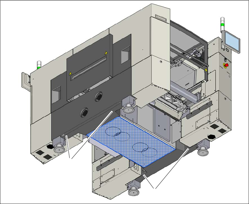
4.3.9.1 Aligning the placement machine with the air cushion transport system
Place the four air cushions from the air cushion transport system under the contact points on
the machine frame.
Raise the placement machine and align it with respect to the line.
Check the distance from the PCB conveyor system of the adjacent placement machine. It
should be between 1 mm and 3 mm.
Lower the placement machine.
4
Fig. 4.3 - 10 Contact positions for the air cushion transport system
(1) 4 contact points for the air cushion transport system
(1)
(1)