00198661-02_UM_SX12-V3_EN.pdf - 第216页
4 Setting up and commissioning Instruction manual SIPLACE SX1/SX 2 Edition V2 and V3 4.3 Setting up the placement machine From software version SC.71 3.1 Edition 12/2020 216 4.3.9 Aligning the placement machin e with the…

Instruction manual SIPLACE SX1/SX2 Edition V2 and V3 4 Setting up and commissioning
From software version SC.713.1 Edition 12/2020 4.3 Setting up the placement machine
215
4
4
Use the machine spirit level to align the placement machine in the X and Y directions (see
4.3.9 on page 216).
Align the PCB conveyors with the help of the long auxiliary board. Move the placement ma-
chine to its final position. You must be able to push the long auxiliary board through the PCB
conveyor to the adjacent placement machine with ease and without jamming.
Use the machine spirit level to check the X and Y directions again and adjust the height of the
feet if necessary.
Tighten the machine feet at the clamping screw to a torque of 130 Nm.
Hit the feet with a hammer to check the load-bearing strength of the machine feet.
Use the machine spirit level to check the X and Y directions again.
WARNING
Risk of damage!
If the machine feet on one side hit the ground hard, the fixings may be damaged.
Slowly lower the placement machine.
A second person should look underneath to ensure that all the machine foot touch
the floor at the same time.
4 Setting up and commissioning Instruction manual SIPLACE SX1/SX2 Edition V2 and V3
4.3 Setting up the placement machine From software version SC.713.1 Edition 12/2020
216
4.3.9 Aligning the placement machine with the machine spirit level
4
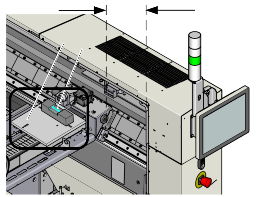
Fig. 4.3 - 8 Adjusting the placement machine in the X and Y direction - measurement structure
Measurement is performed at gantry 1.
Push the gantry inwards, in the Y direction. The distance of the two bumpers should be ap-
prox. 300 mm (or approx. 4-5 red dots on the linear guide).
Place the support plate (1) onto the gantry so that the 3 support pins lie on the free areas be-
tween the running surface and the magnets. Make sure that the 3 support pins touch evenly.
Place the machine spirit level (measuring accuracy of 0.02 mm) onto the support plate and
measure at 3 points
– The alignment of the Y axis at the loose bearing side and at the fixed bearing side.
– The alignment of the X axis in the middle of the X gantry. The head mount must be in the
middle of the X gantry.
4
300 mm
(1)
(
2)

Instruction manual SIPLACE SX1/SX2 Edition V2 and V3 4 Setting up and commissioning
From software version SC.713.1 Edition 12/2020 4.3 Setting up the placement machine
217
4
Adjust the placement machine by following the instructions below in the order listed:
(1) Align the placement machine in the Y direction at the fixed and loose bearing sides. The mea-
suring tolerance is 0.10 mm.
(2) Align the placement machine in the X direction to the middle of the gantry. The measuring
tolerance is 0.10 mm.
(3) Check the load-bearing strength of the 4 machine feet. The 4 machine feet must touch the
ground and be evenly loaded.
(4) Tighten the machine feet at the clamping screw to a torque of 130 Nm.
(5) Hit the feet with a hammer to check the load-bearing strength of the machine feet.
(6) Use the spirit level to ensure that the placement machine is precisely aligned.
PLEASE NOTE
Guaranteed handling accuracy of machine spirit level
Make sure that the spirit level is always placed onto the support plate the same way
round when measuring the X and Y directions