00198661-02_UM_SX12-V3_EN.pdf - 第142页
3 Technical data and assemblies I nstruction manual SIPLACE SX1/S X2 Edition V2 and V3 3.8 Gantry system From software version SC.713.1 Edition 12/2020 142 3 Fig. 3.8 - 3 Design of X axis - view of head mount (1) Y linea…
Instruction manual SIPLACE SX1/SX2 Edition V2 and V3 3 Technical data and assemblies
From software version SC.713.1 Edition 12/2020 3.8 Gantry system
141
3.8.2 Gantry structure
3
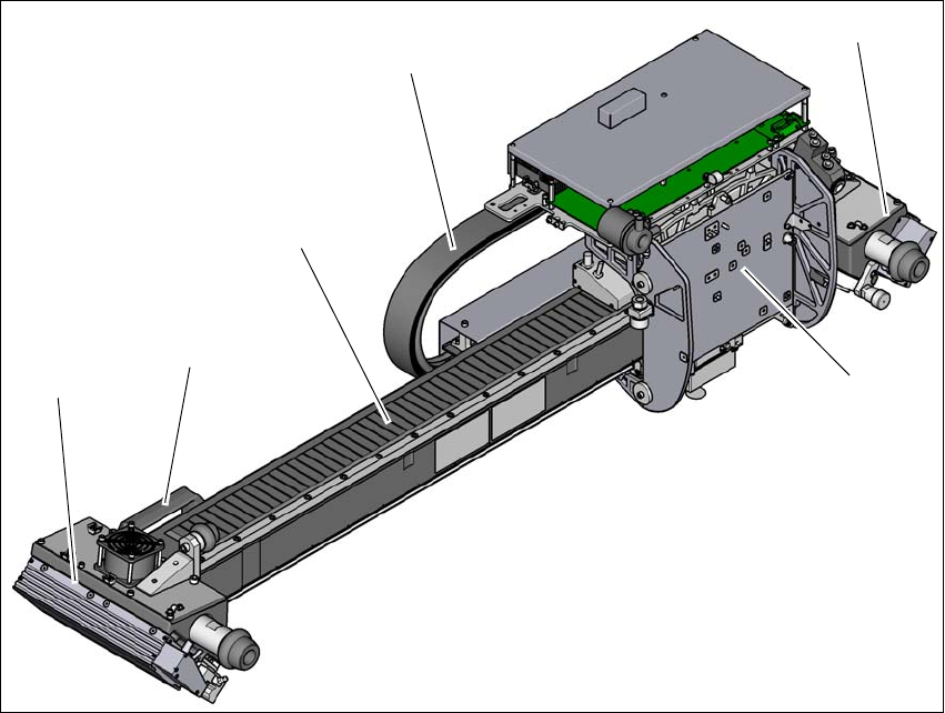
Fig. 3.8 - 2 Gantry structure- view of head mount
(1) Head mount with X axis linear motor (primary part)
(2) Y linear motor 2 with fixed bearing (primary part) and fan
(3) Handle (only for SIPLACE SX1/SX2 V3)
(4) Guidance system with permanent magnet (secondary part of the X linear motor)
(5) Trailing cable
(6) Handle (only for SIPLACE SX1/SX2 V3)
(7) Y linear motor 1 with loose bearing (primary part) and fan
(4)
(3)
(1)
(2)
(6)
(5)
3 Technical data and assemblies Instruction manual SIPLACE SX1/SX2 Edition V2 and V3
3.8 Gantry system From software version SC.713.1 Edition 12/2020
142
3
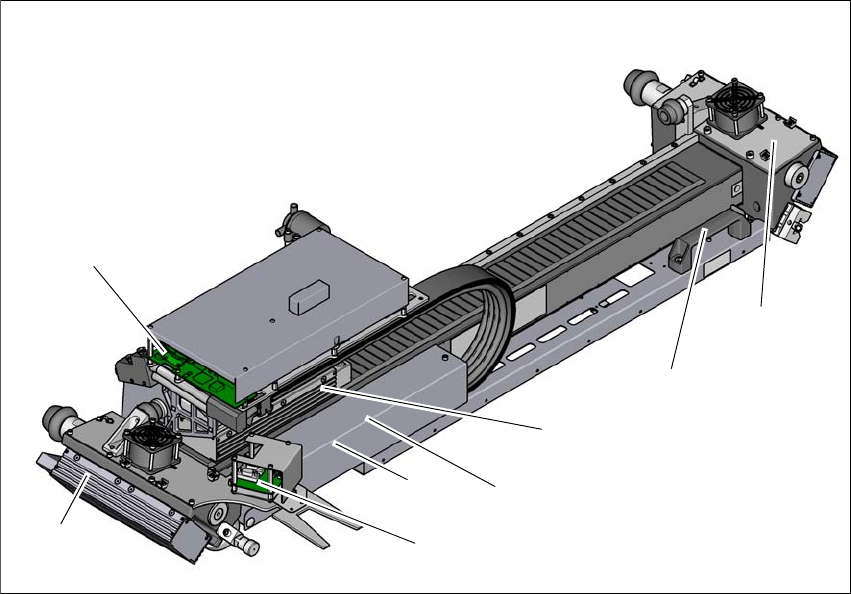
Fig. 3.8 - 3 Design of X axis - view of head mount
(1) Y linear motor 1 with loose bearing (primary part) and fan
(2) Head board with Head Control Unit
(3) Y linear motor 2 with loose bearing (primary part) and fan
(4) Handle (only for SIPLACE SX1/SX2 V3)
(5) X axis linear motor (primary part)
(6) Gantry interface X axis (under the cover)
(7) Gantry interface Y axis (under the cover)
(8) Sensor module
(2)
(1)
(4)
(5)
(6)
(8)
(7)
(3)
Instruction manual SIPLACE SX1/SX2 Edition V2 and V3 3 Technical data and assemblies
From software version SC.713.1 Edition 12/2020 3.8 Gantry system
143
3
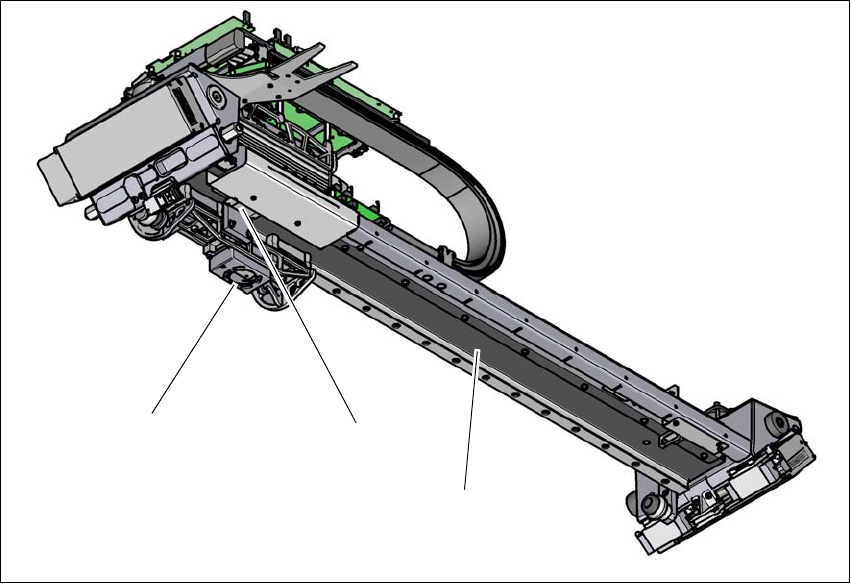
Fig. 3.8 - 4 Gantry structure - view from below
(1) PCB camera
(2) Incremental encoder
(3) Length measurement system (on the gantry underside)
(1)
(2)
(3)