00198661-02_UM_SX12-V3_EN.pdf - 第212页
4 Setting up and commissioning Instruction manual SIPLACE SX1/SX 2 Edition V2 and V3 4.3 Setting up the placement machine From software version SC.71 3.1 Edition 12/2020 212 4.3.7 Machine foot clearances and the stationa…

Instruction manual SIPLACE SX1/SX2 Edition V2 and V3 4 Setting up and commissioning
From software version SC.713.1 Edition 12/2020 4.3 Setting up the placement machine
211
Insert the correct height adapter for the required PCB conveyor height.
Push the height adapter into the clamp so that the notch engages with the locking screw (2).
Loosely tighten the locking screw (2).
Loosely tighten the clamping screw (5) so that the height adapter can be moved in the Z di-
rection with a minimum of play.
Fit the other 3 height adapters in the same manner.
Now use the fork-lift to carefully lower the placement machine until the height adapters touch
the floor evenly. There should always be a second person present to ensure that the place-
ment machine remains stable while it is being lowered. You may need to loosen the height
adapter clamp slightly.
Use the SW 20 open double-ended ring spanner to adjust the height of each height adapter
at the setting screw, so that the relevant conveyor height is achieved.
Align the placement machine in the X and Y direction with the machine spirit level.
4
Tighten the clamping screw to a torque of 130 Nm.
PLEASE NOTE
For a description of how to align the placement machine in the X and Y directions, refer
to the section 4.3.9
, page 216.
4 Setting up and commissioning Instruction manual SIPLACE SX1/SX2 Edition V2 and V3
4.3 Setting up the placement machine From software version SC.713.1 Edition 12/2020
212
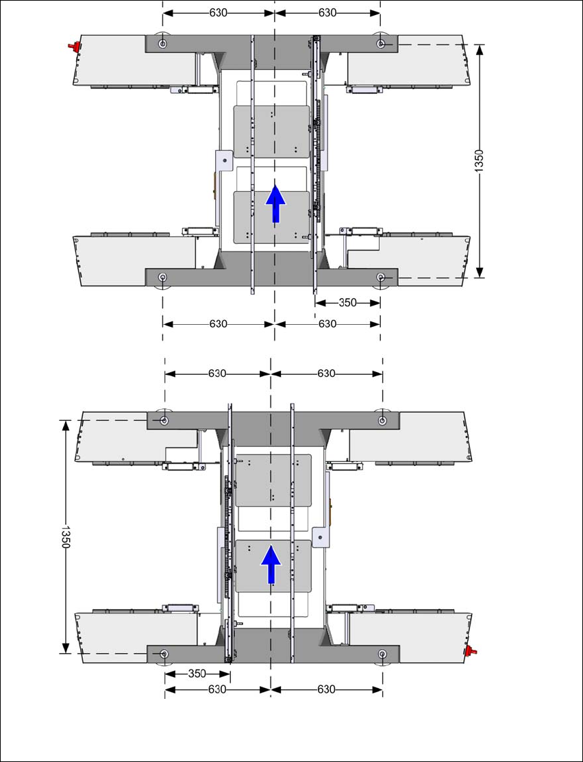
4.3.7 Machine foot clearances and the stationary PCB conveyor edges
4.3.7.1 Machine foot clearances for the PCB single conveyor
4
Fig. 4.3 - 5 Machine foot clearances for the PCB single conveyor in millimeters
Fixed conveyor side at maxi-
mum right position
a
.
Fixed conveyor side at
maximum left position
a
.
a) The value depends on the position of the fixed side.
All dimensions in millimeters.
Instruction manual SIPLACE SX1/SX2 Edition V2 and V3 4 Setting up and commissioning
From software version SC.713.1 Edition 12/2020 4.3 Setting up the placement machine
213
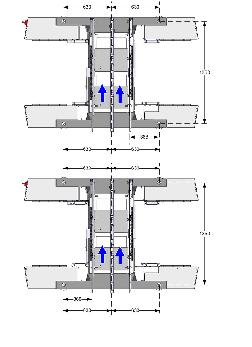
4.3.7.2 Machine foot clearances for the PCB dual conveyor
4
Fig. 4.3 - 6 Machine foot clearances for the PCB dual conveyor in millimeters
Fixed conveyor side at
maximum left position
a
.
Fixed conveyor side at maximum
right position
a
.
a) The value depends on the position of the fixed side.
All dimensions in millimeters.