00198661-02_UM_SX12-V3_EN.pdf - 第331页
Instruction manual SIPLACE SX1/SX2 Edition V2 and V3 6 Station e xtensi ons From software version SC.713.1 Edition 12/2020 6.11 IPC-Hermes-98 52 331 6.10.2.1 Safety instructions 6 6.10.2.2 T echnical dat a 6 6 6.1 1 IPC-…
6 Station extensions Instruction manual SIPLACE SX1/SX2 Edition V2 and V3
6.10 Stationary cameras From software version SC.713.1 Edition 12/2020
330
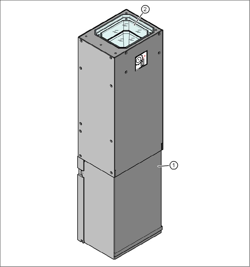
6.10.2 Stationary component camera P&P, type 33 GigE
Item no. 00588100-xx Stationary camera for the CPP head, type 33 GigE
6
Fig. 6.10 - 2 Design of stationary component camera P&P, type 33 GigE
(1) Camera housing with integral camera and camera amplifier
(2) Glass plate - illumination and lens levels below
Instruction manual SIPLACE SX1/SX2 Edition V2 and V3 6 Station extensions
From software version SC.713.1 Edition 12/2020 6.11 IPC-Hermes-9852
331
6.10.2.1 Safety instructions
6
6.10.2.2 Technical data
6
6
6.11 IPC-Hermes-9852
IPC-HERMES-9852 is a communication protocol for SMT lines and can replace the IPC SMEMA
interface. This protocol allows you to transfer more information than previously via the IPC
SMEMA interface.
This could be, for example:
– Unique board IDs
– Barcodes
– Conveyor speed,
– Board length and width
– Board thickness
– Transport clearance height
All this information can be transmitted along the whole line without interruption.
For a detailed description, see the
Administrator Manual IPC-HERMES-9852, item no.
[00198615-xx].
WARNING
Risk of collisions!
When changing the placement head from a TwinStar/VHF to a SpeedStar, the SpeedStar
collides with the camera housing.
Dismantle the stationary component camera for the TwinStar.
When changing the placement head from a TwinStar to a MultiStar, the stationary
component camera is fitted in the bottom position.
Component dimensions 0.5 mm x 0.5 mm to 55 mm x 45 mm
Component range 0402, MELF, SO, PLCC, QFP, electrolytic capacitors, BGA
Min. lead pitch 0.3 mm
Min. lead width 0.15 mm
Min. ball pitch 0.35 mm
Min. ball diameter 0.2 mm
Field of vision 65 mm x 50 mm
Illumination type Front-illumination (6 levels, programmable as required)
6 Station extensions Instruction manual SIPLACE SX1/SX2 Edition V2 and V3
6.12 PCB alignment From software version SC.713.1 Edition 12/2020
332
6.12 PCB alignment
Item no. 00119677-xx PCB alignment, single conveyor
Item no. 00119678-xx PCB alignment, dual conveyor
6.12.1 Description
PCBs to be processed sometimes have a length to width ratio of 1:2 or worse. This means that
the shorter side of the PCB points in the direction of travel. During travel, these boards may twist
slightly and, as a result, the fiducials no longer lie within the PCB camera's search window. In this
case, the "PCB alignment" option ensures that these PCBs are realigned precisely at the stopping
position.
If PCBs with recesses in the direction of travel are processed, this may result in different process-
ing
positions on placement machines with mechanical stoppers and on placement machines that
monitor this position with laser light barriers. The "PCB alignment" option ensures that the PCBs
are stopped at the same position on all PCB conveyors. The "PCB alignment" option is available
for both single and dual conveyors.
The PCB is transported into the placement area until the laser light barrier triggers the stop signal
for the PCB conveyor. The lifting table with the PCB stops then moves up into a position in which
the PCB is not yet clamped and can still be moved by the conveyor belts. The two PCB stops are
level with the PCB, and the PCB supports (magnetic pins) are already in contact with the PCB.
The two conveyor belts move the PCB against the PCB stops and align them at the same time.
The lifting table then moves into its top end position, clamps the PCB and releases it from the PCB
stops so as not to affect the placement process. After the placement process, the lifting table and
PCB alignment are lowered and the PCB is moved on.
6.13 Long board option (LBO)
The "Long board" option allows you to place boards which exceed the specified board length. The
maximum length is 1500 mm.