00198661-02_UM_SX12-V3_EN.pdf - 第149页
Instruction manual SIPLACE SX1/SX2 Edition V2 and V3 3 Technical data and assemblies From software version SC.713.1 Edition 12/2020 3.9 PCB conveyor s ystem 149 3.9.3.3 Asynchronous transport mode In asynchronous mode, o…
3 Technical data and assemblies Instruction manual SIPLACE SX1/SX2 Edition V2 and V3
3.9 PCB conveyor system From software version SC.713.1 Edition 12/2020
148
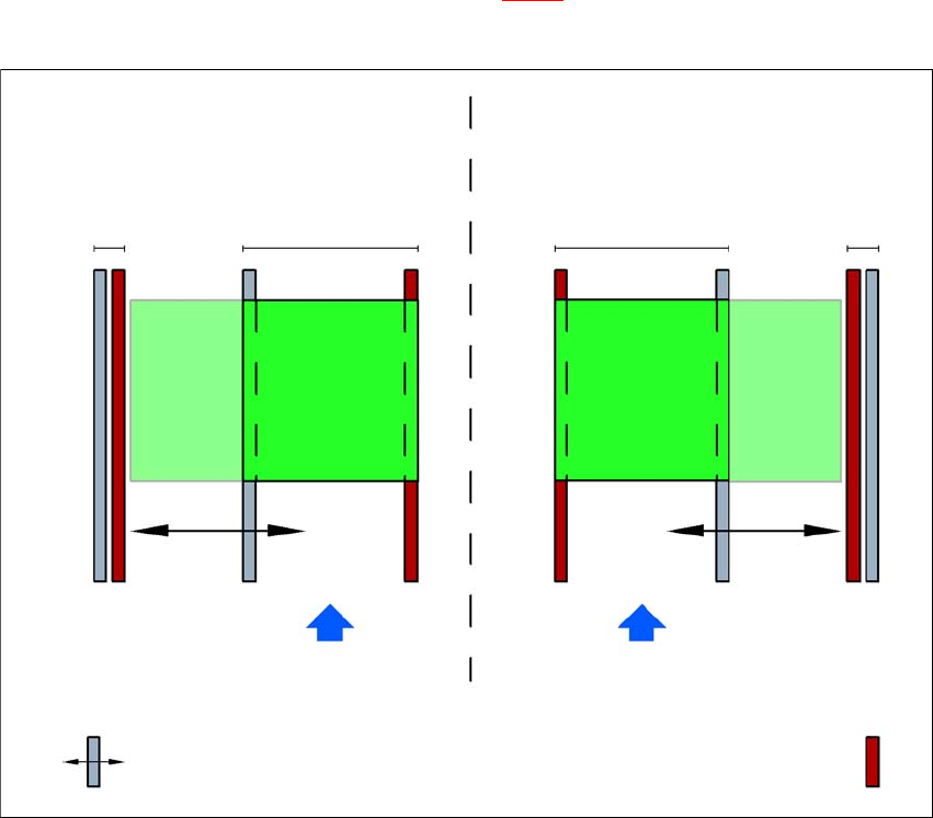
3.9.3.2 PCB dual conveyor in single conveyor mode
The dual conveyor can be configured online to create a single conveyor. One conveyor lane is
moved together completely and is disabled (see fig. 3.9 - 3
). This gives a conveyor track width of
up to 460 mm.
3
Fig. 3.9 - 3 Flexible dual conveyor in Single conveyor mode
Dual conveyor with widened conveyor track 2
(stationary conveyor side wall on left)
Conveyor track 2
deactivated
Conveyor track 1 Conveyor track 2 Conveyor track 1
deactivated
PCB transport direction PCB transport direction
Stationary conveyor side wall
Dual conveyor with widened conveyor track 1
(stationary conveyor side wall on right)
Movable conveyor side wall
Instruction manual SIPLACE SX1/SX2 Edition V2 and V3 3 Technical data and assemblies
From software version SC.713.1 Edition 12/2020 3.9 PCB conveyor system
149
3.9.3.3 Asynchronous transport mode
In asynchronous mode, only one PCB in a transport track is processed. At the same time, another
PCB in the second transport track is moved into the placement position. This saves the full con-
veying time of one PCB, thus considerably increasing performance, particularly for PCBs with a
short cycle time.
Once the placement machine has received the job data (panel, setup), the boards on the input
conveyors are continuously transported to the available processing conveyor (provided that the
processing conveyor is free) throughout the placement operation. The placement sequence starts
as soon as a PCB has moved onto the processing belt. The PCBs are processed one after an-
other.
If the placement sequence is interrupted, the conveyor interface will be disabled and the PCBs
currently on the processing belts will be completed.
The conveyor interface is disabled or enabled simultaneously for both transport tracks.
3
Fig. 3.9 - 4 Transport modes
Synchronous transport mode
Asynchronous transport mode
3 Technical data and assemblies Instruction manual SIPLACE SX1/SX2 Edition V2 and V3
3.9 PCB conveyor system From software version SC.713.1 Edition 12/2020
150
3.9.3.4 Synchronous transport mode
In synchronous mode, two PCBs of the same size are moved into the placement position at the
same time. They must be processed as a common panel.
This makes it possible to process the top and bottom sides of a board in one line. The time needed
to transport the board is reduced as two boards are always transported at the same time. It also
ensures better utilization of the nozzle configuration.
PCBs on conveyor tracks 1 and 2 are moved synchronously onto the conveyor sections (i.e. the
conveyors are controlled synchronously, but independently of one another). The components to
be placed on conveyor tracks 1 and 2 must be organized into a panel via two subpanels.
If only one conveyor lane is occupied at the beginning of placement, this single use of the con-
veyor lane will be identified as "not to be placed".
If the dual conveyor is operated in synchronous mode, the ‘PCB whispering down the line’ option
is deactivated. The "Global bad fiducial" option cannot be used.
3.9.3.5 I-Placement
In addition to the synchronous and asynchronous conveyor modes, the placement concept "I-
Placement" has now been introduced. In this case, both placement heads operate in one place-
ment area at the same time, placing their own boards fully independently of one another. In normal
mode, the placement heads operate in alternating placement mode: while the placement head in
one placement area places a board, the other placement head picks up components from the
feeder module. In the case of "I-Placement", the placement heads do not have this waiting period,
which increases the placement performance.
3.9.4 Controlling and width adjustment
3.9.4.1 Controlling using the Single Functions menu
The online help contains information on controlling the PCB conveyor system and on the Single
Functions menu.
3.9.4.2 Automatic width adjustment
When the command is received, the conveyor belts are set to the desired width. Different widths
are possible for a dual conveyor.
See the Online Help for detailed information about changing the conveyor track width.