00198661-02_UM_SX12-V3_EN.pdf - 第266页
5 Tasks at the placement machine Instruction manual SIPLACE SX1/ SX2 Edition V2 and V3 5.10 Setting up the feeder modules From software version SC.713. 1 Edition 12/2020 266 5.10 Setting up the feeder modules 5.10.1 Note…
Instruction manual SIPLACE SX1/SX2 Edition V2 and V3 5 Tasks at the placement machine
From software version SC.713.1 Edition 12/2020 5.9 Carrying out a sight check
265
5
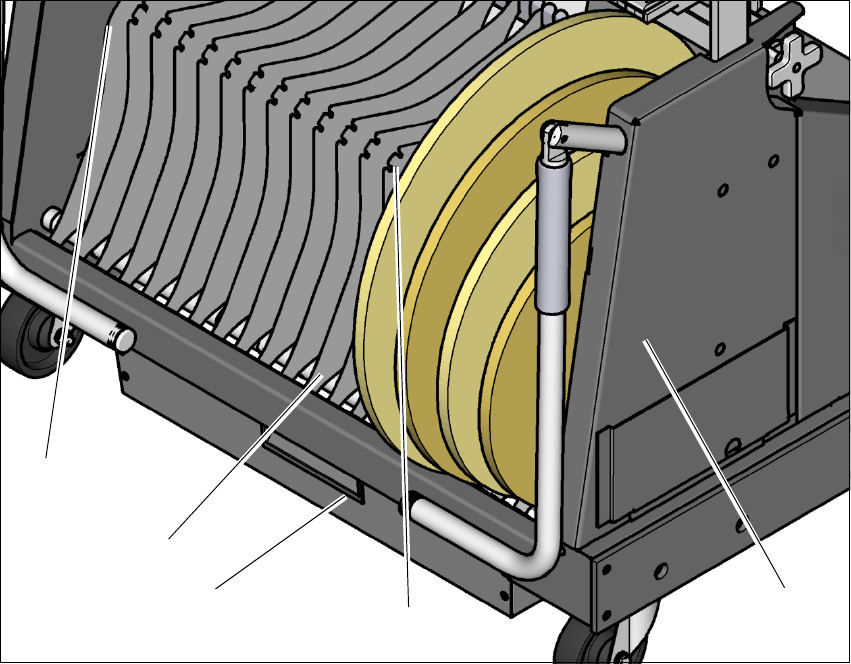
Fig. 5.9 - 3 Separating plates in the tape container
(1) Position of the separating plate if no spindles are used
(2) Guide rail for the separating plates
(3) Waste tape container
(4) Position of the separating plate if spindles are used
(5) Tape container
(1)
(5)
(2)
(3)
(4)
5 Tasks at the placement machine Instruction manual SIPLACE SX1/SX2 Edition V2 and V3
5.10 Setting up the feeder modules From software version SC.713.1 Edition 12/2020
266
5.10 Setting up the feeder modules
5.10.1 Notes on handling feeder modules
Feeder modules are precision devices. You should therefore handle the feeder modules with care.
Avoid bumping feeder modules into obstacles.
Do not drop the feeder modules.
Always use suitable tools for preventive maintenance.
5.10.2 Removing X feeder modules from the changeover table
5
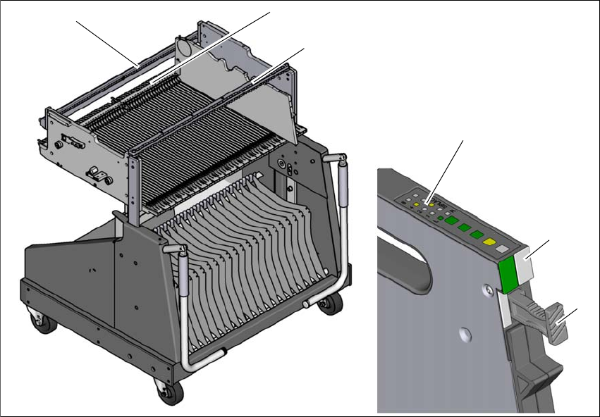
Fig. 5.10 - 1 Removing X feeder modules from the changeover table
(1) Removal handle
(2) Status display
(3) LED display
(4) Rail for checking height of feeder
(5) Latch for locking the feeder modules
(6) Centering rail
5
(2)
(1)
(4)
(5)
(6)
(3)

Instruction manual SIPLACE SX1/SX2 Edition V2 and V3 5 Tasks at the placement machine
From software version SC.713.1 Edition 12/2020 5.10 Setting up the feeder modules
267
On standby, the status display (item 2 in fig. 5.10 - 1
, page 266) lights up green if the X axis feeder
module is contained in the current setup. If the feeder module is not contained in the current setup,
the status display remains off.
The feeder module is locked in position in the changeover table by a latch, and cannot be pulled
out. The procedure for removing feeder modules from the changeover table is as follows:
Press the removal handle (item 1 in fig. 5.10 - 1, page 266). The removal handle jumps out
and the status display goes out.
Wait approximately 1 second until the lock (item 4 in fig. 5.10 - 1, page 266) releases the
feeder module.
Use the removal handle to pull the feeder module out of the changeover table. If you wait lon-
ger than 5 seconds, the feeder module will be locked once more. The status display will shine
red.
Engage the removal handle once more. If the feeder module is contained in the current setup,
the status display lights up green and the track number and increment will appear on the LCD
display once more.