00198661-02_UM_SX12-V3_EN.pdf - 第290页
5 Tasks at the placement machine Instruction manual SIPLACE SX1/ SX2 Edition V2 and V3 5.15 Docking the component trolley in or out From software versi on SC.713.1 Edition 12/2020 290
Instruction manual SIPLACE SX1/SX2 Edition V2 and V3 5 Tasks at the placement machine
From software version SC.713.1 Edition 12/2020 5.15 Docking the component trolley in or out
289
5
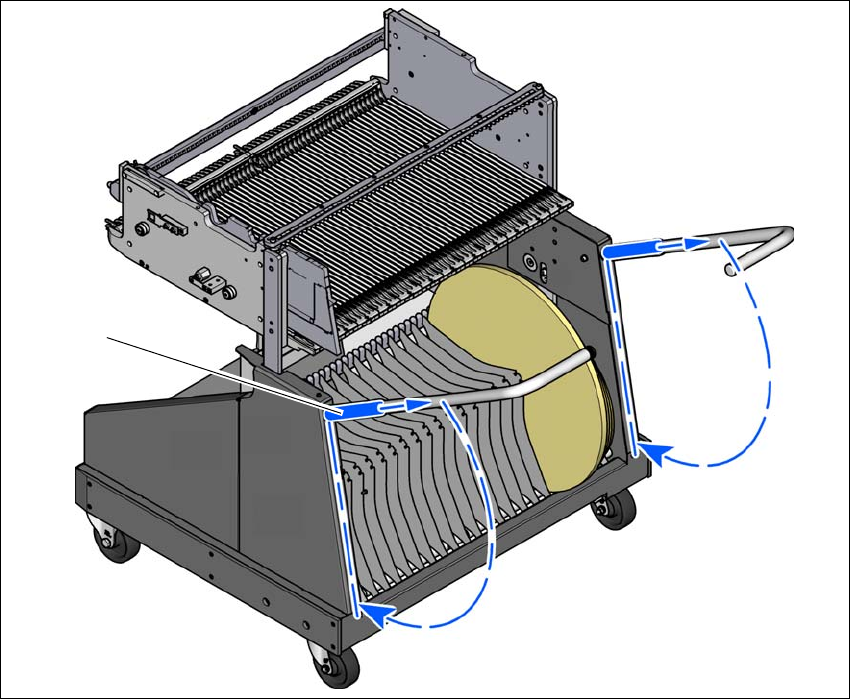
Fig. 5.15 - 6 Component trolley - swivel handles down
(1) Push sleeve up
(2) Fold handle down
(1)
(2)
(2)
5 Tasks at the placement machine Instruction manual SIPLACE SX1/SX2 Edition V2 and V3
5.15 Docking the component trolley in or out From software version SC.713.1 Edition 12/2020
290

Instruction manual SIPLACE SX1/SX2 Edition V2 and V3 6 Station extensions
From software version SC.713.1 Edition 12/2020 6.1 Nozzle changer
291
6 Station extensions
For the relevant configurations and other options, refer to the individual specifications for the SI-
PLACE placement machines.
6
6.1 Nozzle changer
The magazines are seated on a common support. They are centered with two parallel pins and
fixed in place with 4 push buttons. The exact position is determined with two fiducials on each
magazine. The correct seat of the magazines on the basic nozzle changer body is monitored by
microswitches, to prevent a collision of the placement head with any magazines projecting up-
wards. All magazine locations must be filled since the safety circuit stops the placement machine
in response to missing magazines or magazines that are not seated correctly.
PLEASE NOTE
When using the SIPLACE Smart Pin Support option, the maximum number of nozzle
changer magazines is reduced