00198661-02_UM_SX12-V3_EN.pdf - 第209页
Instruction manual SIPLACE SX1/SX2 Edition V2 and V3 4 Setting up and commissioning From software version SC.713.1 Edition 12/2020 4.3 Setting up the placement machine 209 4 Fig. 4.3 - 3 Machine feet (height adapter) for…
4 Setting up and commissioning Instruction manual SIPLACE SX1/SX2 Edition V2 and V3
4.3 Setting up the placement machine From software version SC.713.1 Edition 12/2020
208
4.3.6 Replacing machine feet (height adapter)
The placement machine stands on 4 feet (height adapter) (see item 1 in fig. 4.3 - 2, page 208)
The corresponding height adapters are available for the various PCB conveyor heights.
4
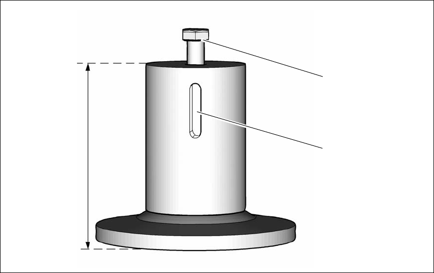
Fig. 4.3 - 2 Height adapter for placement machine
(1) Hexagon socket head screw for height adjustment
(2) Notch for fixture against falling (locking screw)
(3) Various height adapter dimensions
– Height adapter for PCB conveyor height 900 (Item No. 03067048-xx)
– Height adapter for PCB conveyor height 930 (Item No. 03067046-xx)
– Height adapter for PCB conveyor height 950 (Item No. 03065876-xx)
(3)
(1)
(2)
Instruction manual SIPLACE SX1/SX2 Edition V2 and V3 4 Setting up and commissioning
From software version SC.713.1 Edition 12/2020 4.3 Setting up the placement machine
209
4
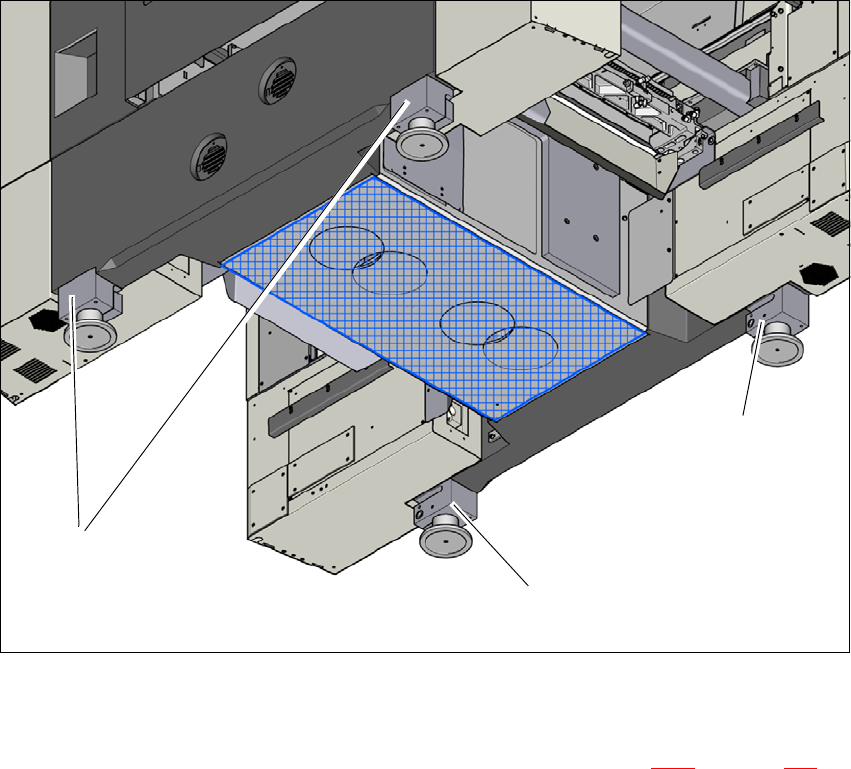
Fig. 4.3 - 3 Machine feet (height adapter) for placement machine
(1) 4 height adapters - for various heights
Push the forks of the fork lift under the placement machine. See also 4.3.2, on page 204.
With the fork-lift, raise the placement machine approximately 35 cm. You can now pull the
height adapters down and out.
(1)
(1)
(1)
4 Setting up and commissioning Instruction manual SIPLACE SX1/SX2 Edition V2 and V3
4.3 Setting up the placement machine From software version SC.713.1 Edition 12/2020
210
4
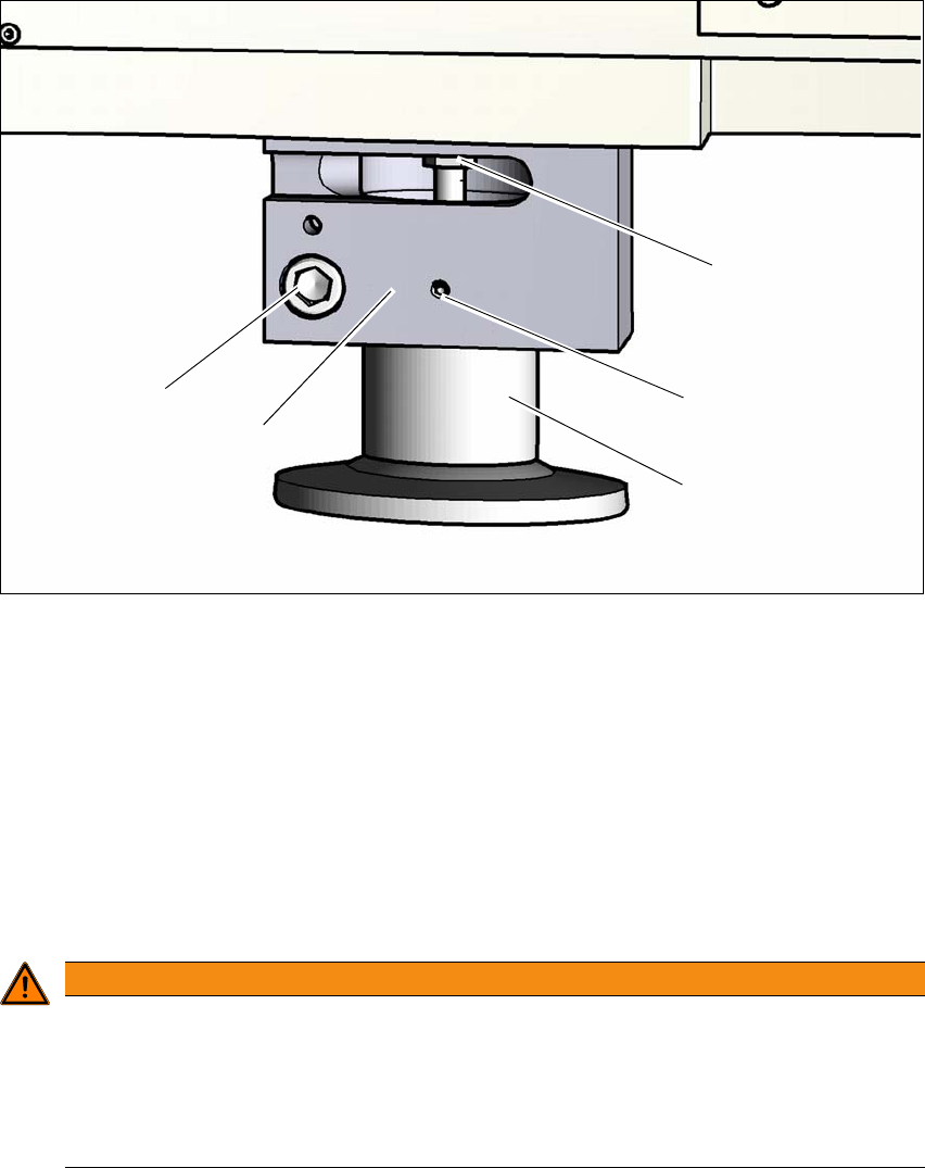
Fig. 4.3 - 4 Height adapter - adjusting the height
4
(1) Setting screw for adjusting the height
(2) Locking screw
(3) Height adapter
(4) Clamping
(5) Clamping screw
Loosen the locking screw (2). This locking screw fixes the height adapter and prevents it fall-
ing down as soon as the clamp has been loosened.
4
Loosen the clamping screw and pull the height adapter down and out.
Check the new height adapter to make sure that the height adjustment screw (1) can be
moved easily. If necessary, loosen the screw and grease the thread with Topas NCA 52.
To make sure that the height adapter can be easily pushed into the clamp (4), grease the
clamping area of the height adapter with Topas NCA 52.
WARNING
Risk of injuries!
After loosening the clamps, the height adapter could still fall out, despite being secured
with the grub screw in the groove, and could then injure hands and feet.
Hold the height adapter while fastening, to prevent it falling down.
Take care that your hands and feet can not be hit.
(3)
(1)
(2)
(4)
(5)