00198661-02_UM_SX12-V3_EN.pdf - 第221页
Instruction manual SIPLACE SX1/SX2 Edition V2 and V3 4 Setting up and commissioning From software version SC.713.1 Edition 12/2020 4.4 Adjusting the component trolley to the PCB conve yor height 221 4.4 Adjusting the com…
4 Setting up and commissioning Instruction manual SIPLACE SX1/SX2 Edition V2 and V3
4.3 Setting up the placement machine From software version SC.713.1 Edition 12/2020
220
4.3.10 Removing the shipping braces
The shipping braces are attached to the linear guides. Each gantry is fastened with two shipping
braces on the X and Y axes.
Remove all the shipping braces from the gantry axes.
If the SIPLACE placement machine needs to be transported, always fit the shipping braces
back onto the conveyor.
4.3.11 Removing the corrosion protection from the guide rails
The placement machines were given a corrosion protection treatment before they were delivered.
4
4
CAUTION
Reduced product life of bearings and guide rails!
If the corrosion protection agent is mixed with the bearing grease on the axes this can
greatly reduce the service life of the bearings and guide rails.
You should therefore remove the corrosion protection from all the axes and bearings
when you traverse the machine axes for the first time during commissioning.
Grease all the axes and bearings with the grease described in the maintenance in-
structions.
CAUTION
Risk of damaging bearing grease!
Alcohol will damage the bearing grease in the guide carriages.
When cleaning the guide rails and scales, make sure that alcohol does not get into
the guide trolley.
Instruction manual SIPLACE SX1/SX2 Edition V2 and V3 4 Setting up and commissioning
From software version SC.713.1 Edition 12/2020 4.4 Adjusting the component trolley to the PCB conveyor height
221
4.4 Adjusting the component trolley to the PCB conveyor
height
The component trolley can be easily and quickly adjusted to the following PCB conveyor heights:
900 mm
4
930 mm (standard height) 4
950 mm (SMEMA height) 4
4
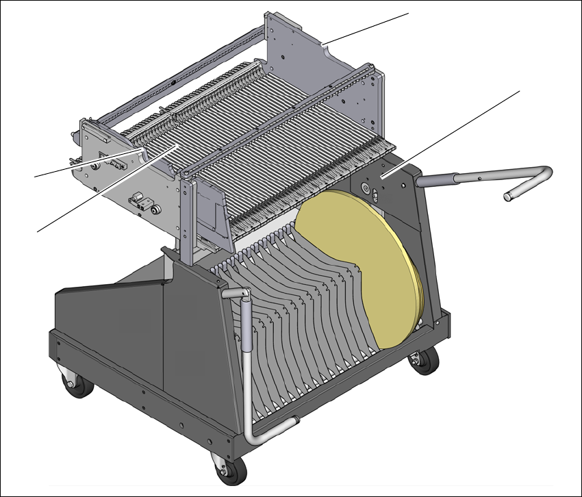
Fig. 4.4 - 1 Component trolley 60
(1) Holes for the transport heights of 900, 930 and 950 mm.
(2) Changeover table
(3) M8 holes for fixing the mounting device
(1)
(2)
(3)
(3)
4 Setting up and commissioning Instruction manual SIPLACE SX1/SX2 Edition V2 and V3
4.4 Adjusting the component trolley to the PCB conveyor height From software version SC.713.1 Edition 12/2020
222
4.4.1 Warning instructions
4
4.4.2 Tools and equipment
You will need the following tools and equipment to adjust the height of the component trolley:
– Mounting device (item no. 03015976-xx)
– Lifting device for raising the component trolley table, carrying capacity at least 80 kg
4.4.3 Changing the component trolley height
4
Fix the fit-up aid to the changeover table with the two M8 x 50 hexagon socket head screws.
There are two different holes available for the changeover table 60 and the changeover table
30.
Hook the leverage device into the eyelet.
Loosen the fastening screws and lift the changeover table into the required position.
Fit and tighten the fastening screws.
WARNING
Adjustment of component trolley height by certified persons!
Only ASM engineers or qualified personnel are permitted to adjust the component trolley
height.
Always follow the applicable accident prevention regulations.
Remove all the feeder modules from the changeover table, if you want to adjust the
height of the changeover table.
WARNING
Risk of damage!
Lifting and lowering the changeover table can lead to deformation of it.
Remove all the feeder modules from the changeover table.
Fit the mounting device to the changeover table in order to adjust the height.