00198661-02_UM_SX12-V3_EN.pdf - 第119页
Instruction manual SIPLACE SX1/SX2 Edition V2 and V3 3 Technical data and assemblies From software version SC.713.1 Edition 12/2020 3.7 Placement head 119 3.7 Placement head 3.7.1 SIPLACE SpeedS tar C&P20 P2 on the S…
3 Technical data and assemblies Instruction manual SIPLACE SX1/SX2 Edition V2 and V3
3.6 Overviews of the modules From software version SC.713.1 Edition 12/2020
118
3.6.4 Overview of SIPLACE SX1 V2 assemblies
3
3
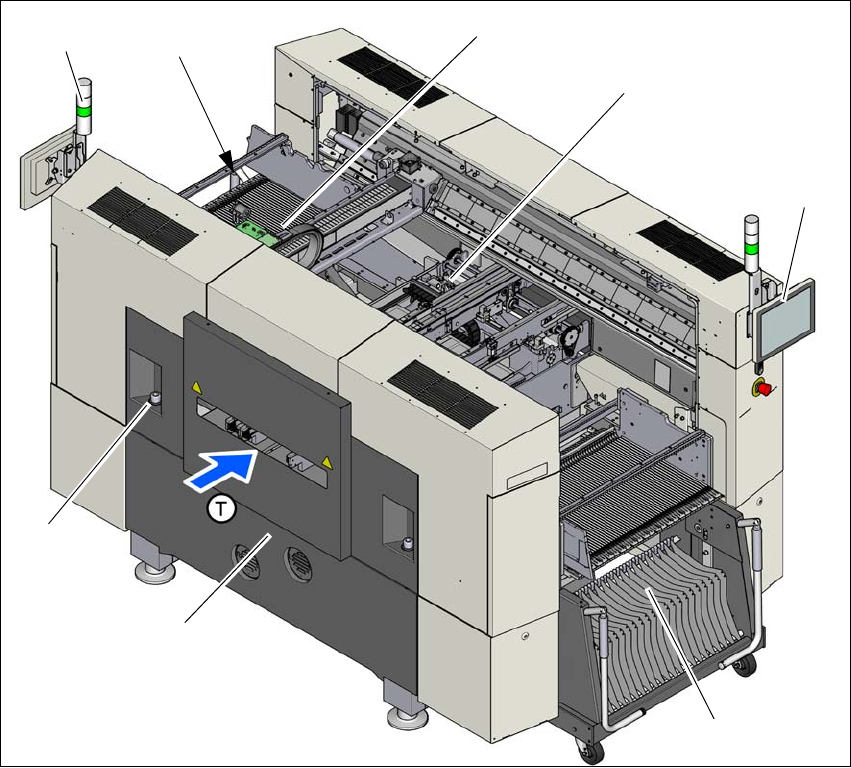
Fig. 3.6 - 4 SIPLACE SX2 V2-placement machine - overview of assemblies
(1) Basic module
(2) Robot module
(3) Gantry 1 with placement head
(4) PCB conveyor (single or dual conveyor)
(5) Monitor with keyboard (2x)
(6) Location 2 with component trolley
(7) Location 1 with COT insert, tape cutter, empty tape duct
(T) Direction of PCB transport
(1)
(2)
(3)
(4)
(5)
(6)
(5)
(7)

Instruction manual SIPLACE SX1/SX2 Edition V2 and V3 3 Technical data and assemblies
From software version SC.713.1 Edition 12/2020 3.7 Placement head
119
3.7 Placement head
3.7.1 SIPLACE SpeedStar C&P20 P2 on the SIPLACE SX1/SX2 V3
The SIPLACE SX1/SX2 V3 uses the SIPLACE SpeedStar C&P20 P2 for top placement perfor-
mance.
3
CAUTION
Always take hold of the handle to push the placement head
The placement head may only be moved by pushing manually against the handle provid-
ed.
3 Technical data and assemblies Instruction manual SIPLACE SX1/SX2 Edition V2 and V3
3.7 Placement head From software version SC.713.1 Edition 12/2020
120
3.7.1.1 Overview
3
3
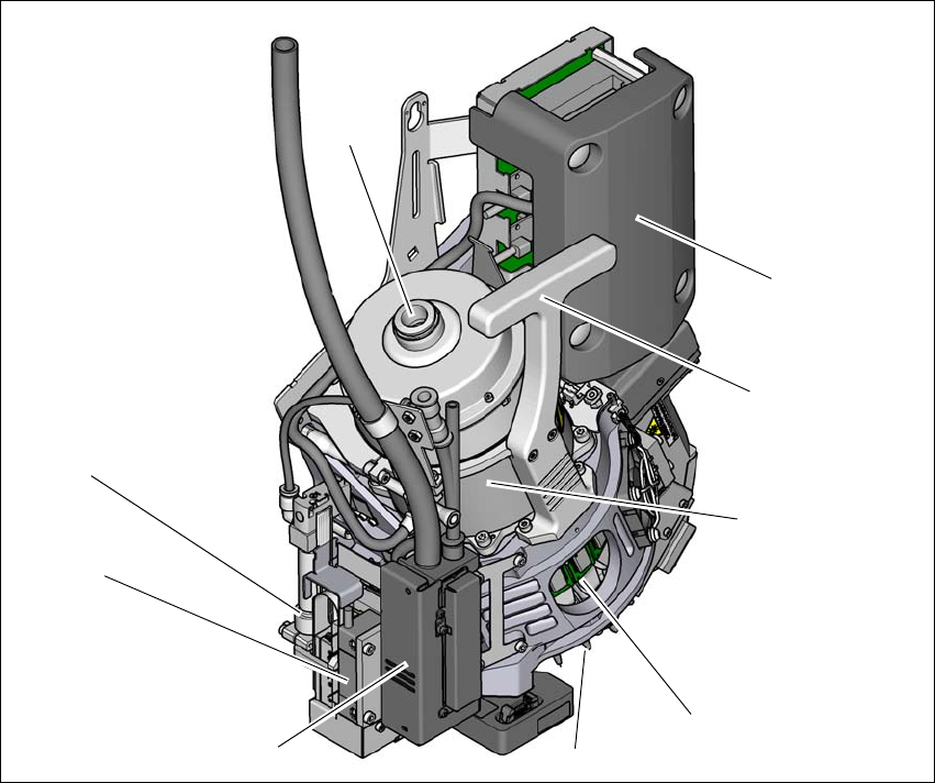
Fig. 3.7 - 1 SIPLACE SpeedStar - overview
(1) Connection for the holding circuit of the vacuum pump
(2) "Intermediate distributor" board (under the cover)
(3) Handle
(4) Star motor
(5) DP drive
(6) Nozzle
(7) Pressure control valve
(8) Z motor (linear motor)
(9) Return cylinder
(5)
(1)
(7)
(2)
(3)
(4)
(6)
(8)
(9)