00198661-02_UM_SX12-V3_EN.pdf - 第97页
Instruction manual SIPLACE SX1/SX2 Edition V2 and V3 2 Operation al safety From software version SC.713.1 Edition 12/2020 2.9 Locking and at taching the war ning labels 97 2.9 Locking and att aching the warning labels 2.…
2 Operational safety Instruction manual SIPLACE SX1/SX2 Edition V2 and V3
2.8 Disabling the compressed air supply and discharging the pressure From software version SC.713.1 Edition 12/2020
96
2
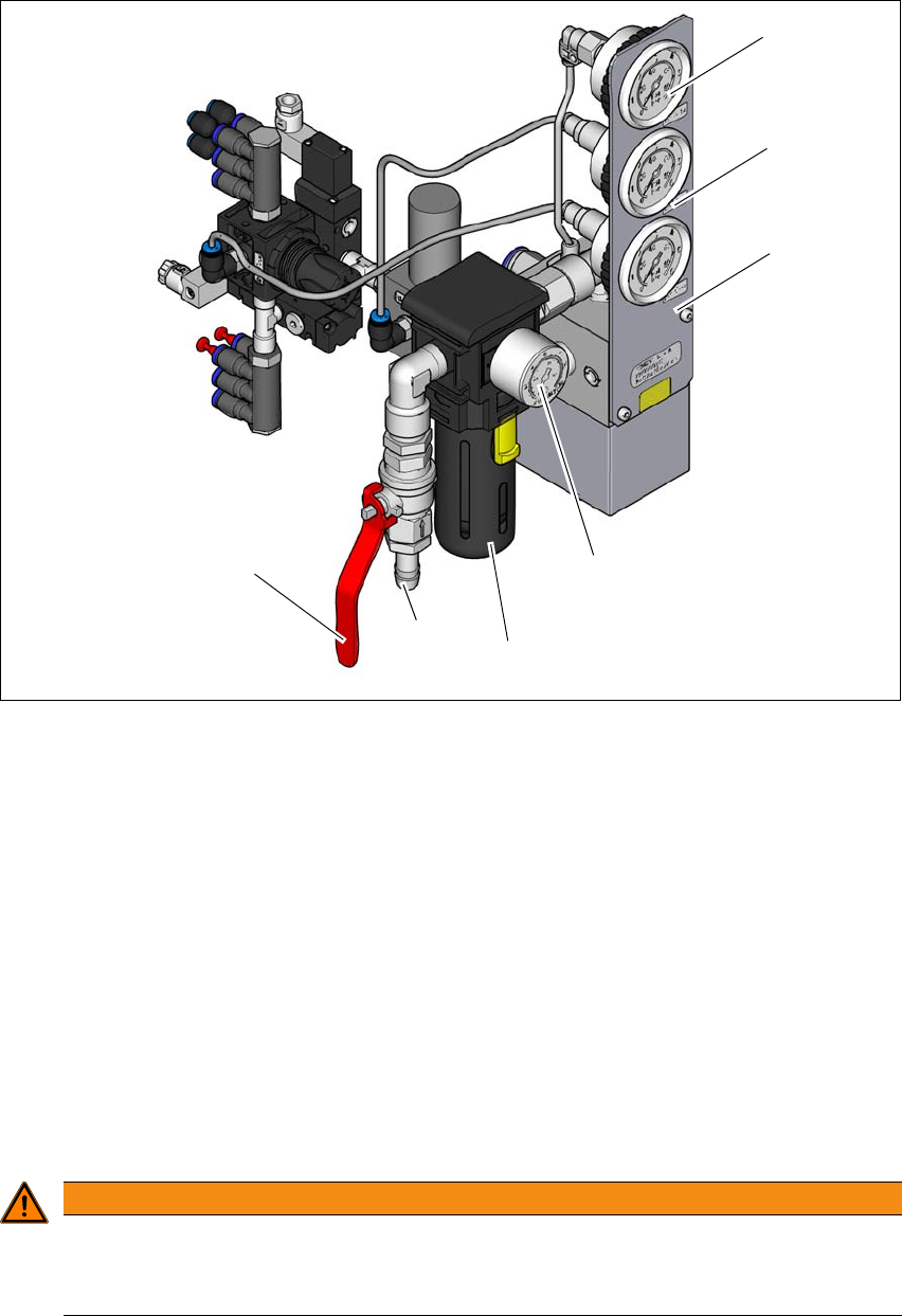
Fig. 2.8 - 1 Compressed air unit on the placement machine
(1) Manometer for supply pressure of gantries 1 and 2
Target pressure: 0.46 ± 0.01 MPa, 4.6 ± 0.1 bar (display range 0 - 0.6 MPa, 0 - 6 bar)
(2) Manometer for the machine component supply pressure
Target pressure: 0.5 ± 0.025 MPa, 4.5 ± 0.25 bar (display range 0 - 0.6 MPa, 0 - 6 bar)
(3) Manometer for the bulkcase feeder module supply pressure
Target pressure: 0.25 ± 0.05 MPa, 2.5 ± 0.5 bar (display range: 0 - 0.6 MPa, 0 - 6 bar)
(4) Manometer for inlet pressure
Target pressure: 0.5 - 1.0 MPa, 5.0 - 10.0 bar (display range: 0 - 1.0 MPa, 0 - 10 bar)
(5) Compressed air filter
(6) Compressed air connection
(7) Stop valve in the "OPEN" position
2
WARNING
Risk of injuries!
Risk of injuries from pressurized compressed air lines.
NEVER detach compressed air lines while they are still pressurized.
(6)
(1)
(2)
(3)
(4)
(5)
(7)

Instruction manual SIPLACE SX1/SX2 Edition V2 and V3 2 Operational safety
From software version SC.713.1 Edition 12/2020 2.9 Locking and attaching the warning labels
97
2.9 Locking and attaching the warning labels
2.9.1 Purpose and scope
Before performing any preventive maintenance work or service work to the placement machine,
a procedure of locking and tagging must be followed. The following procedure, when followed cor-
rectly, eliminates the possibility of an employee being injured by electrical shock in connection with
unexpected movement.
2
2.9.2 Description
Whenever it becomes necessary to isolate, control and release energy for the placement ma-
chine, the following procedure is to be followed.
Notify affected employees.
Switch off the placement machine and any auxiliary devices. Carry out all normal stopping
procedures:
– Press the stop button.
– Shut down the control computer.
– Switch the placement machine off at the main power switch.
Isolate the placement machine from all its energy sources:
– Shut off the compressed air supply
– Shut off the main power supply
Lock out the machine.
– Attach a lock whenever possible (e.g. to the main switch).
PLEASE NOTE
Minimum requirements
These procedures represent the minimum lock/tag out requirements for the preventive
maintenance or service work on the placement machine. Any additional safeguards
needed to complete work safely can be specified by facilities supervision, the safety of-
ficer, the safety committee and the health department.

2 Operational safety Instruction manual SIPLACE SX1/SX2 Edition V2 and V3
2.9 Locking and attaching the warning labels From software version SC.713.1 Edition 12/2020
98
Alternatively: Tag out procedure
If the placement machine can be locked out, it must be. However, there are situations where
it is not possible to attach a lock in order to isolate the energy. In these cases, the energy-
isolated placement machine must be tagged to warn employees that the placement machine
is isolated for servicing. The tag must be securely fastened, it must be placed in a position
visible to all and it may only be removed by the person who attached it.
2
Release stored energy
Stored energy in the compressed air supply or electrical energy in electrolytic capacitors
must be released by appropriate means.
2
After switching off the placement machine, wait the specified discharge or pressure un-
loading time (see sections 2.7
, page 92, and 2.8, page 95), before the placement ma-
chine can be operated again without risk.
Verify the lock out.
Testing the lock out for the placement machine can be done simply by pressing the start but-
ton.
The following steps must be taken to restore the placement machine to operation:
Check the area. Authorized employees should remove all of their tools and reinstall all
guards.
Notify all affected employees.
Before removing even one lock or tag, inform all workers in the area that the placement
machine is going to be restarted.
Remove locks/tags
Each authorized employee must remove his or her own lock. Each authorized employee
will have his or her own lock.
Turn the placement machine on. Authorized workers should observe the equipment in
operation to insure repairs were done correctly.
2.9.3 Testing
Service personnel may test the circuits by activating them briefly without canceling the locking
method. This may be done only when no other work is being performed by any other person on
the equipment being tested.
It is extremely important that all remote start switches be tagged with the Do Not Operate tag to
prevent inadvertent operation of the equipment during these periods.